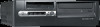
HP Workstation xw3100 HP Workstation xw3100 - Service and Technical Reference - Page 5

Diskette Drive Bezel or Bezel Blank, Unlocking the Smart Cover Lock .5-2 - memory

Page 5 highlights

Contents 5 Removal and Replacement Procedures 5.1 Preparation for Disassembly 5-1 5.2 Unlocking the Smart Cover Lock 5-2 5.3 Hood Sensor 5-3 5.4 External Security Devices 5-4 5.4.1 Cable Lock 5-4 5.4.2 Padlock 5-5 5.5 Workstation Access Panel 5-6 5.6 Front Bezel 5-7 5.7 Front Drive Bezels 5-8 5.7.1 Diskette Drive Bezel or Bezel Blank 5-8 5.8 Memory 5-9 5.9 Expansion Card Cage 5-10 5.9.1 Riser Card 5-11 5.9.2 Expansion Card 5-12 5.9.3 AGP Card 5-13 5.10Drives 5-15 5.10.1Extra Screws 5-15 5.10.2Drive Positions 5-15 5.10.3Optical Drive 5-16 5.10.4External 3.5-inch Drive 5-19 5.10.5Primary Hard Drive 5-21 5.11Front I/O Devices 5-23 5.12Power Switch Assembly 5-24 5.13System Board 5-25 5.14Battery 5-26 5.14.1Type 1 Battery Holder 5-27 5.14.2Type 2 Battery Holder 5-28 5.15Processor and Heatsink 5-29 5.16Speaker 5-30 5.17Power Supply 5-31 A Connector Pin Assignments B Power Cord Set Requirements C POST Error Messages D Troubleshooting Without Diagnostics E System Board and Riser Board Reference Designators F Memory G Ultra ATA Drive Guidelines and Features Index Service and Technical Reference Guide, xw3100 338611-001 v

  • 1
  • 2
  • 3
  • 4
  • 5
  • 6
  • 7
  • 8
  • 9
  • 10
  • 11
  • 12
  • 13
  • 14
  • 15
  • 16
  • 17
  • 18
  • 19
  • 20
  • 21
  • 22
  • 23
  • 24
  • 25
  • 26
  • 27
  • 28
  • 29
  • 30
  • 31
  • 32
  • 33
  • 34
  • 35
  • 36
  • 37
  • 38
  • 39
  • 40
  • 41
  • 42
  • 43
  • 44
  • 45
  • 46
  • 47
  • 48
  • 49
  • 50
  • 51
  • 52
  • 53
  • 54
  • 55
  • 56
  • 57
  • 58
  • 59
  • 60
  • 61
  • 62
  • 63
  • 64
  • 65
  • 66
  • 67
  • 68
  • 69
  • 70
  • 71
  • 72
  • 73
  • 74
  • 75
  • 76
  • 77
  • 78
  • 79
  • 80
  • 81
  • 82
  • 83
  • 84
  • 85
  • 86
  • 87
  • 88
  • 89
  • 90
  • 91
  • 92
  • 93
  • 94
  • 95
  • 96
  • 97
  • 98
  • 99
  • 100
  • 101
  • 102
  • 103
  • 104
  • 105
  • 106
  • 107
  • 108
  • 109
  • 110
  • 111
  • 112
  • 113
  • 114
  • 115
  • 116
  • 117
  • 118
  • 119
  • 120
  • 121
  • 122
  • 123
  • 124
  • 125
  • 126
  • 127
  • 128
  • 129
  • 130
  • 131
  • 132
  • 133
  • 134
  • 135
  • 136
  • 137
  • 138
  • 139
  • 140
  • 141
  • 142
  • 143
  • 144
  • 145
  • 146
  • 147
  • 148

Service and Technical Reference Guide, xw3100
338611-001
v
Contents
5
Removal and Replacement Procedures
5.1
Preparation for Disassembly . . . . . . . . . . . . . . . . . . . . . . . . . . . . . . . . . . . . . . . . . . . . . . . . . . . . 5–1
5.2
Unlocking the Smart Cover Lock . . . . . . . . . . . . . . . . . . . . . . . . . . . . . . . . . . . . . . . . . . . . . . . . 5–2
5.3
Hood Sensor . . . . . . . . . . . . . . . . . . . . . . . . . . . . . . . . . . . . . . . . . . . . . . . . . . . . . . . . . . . . . . . . 5–3
5.4
External Security Devices . . . . . . . . . . . . . . . . . . . . . . . . . . . . . . . . . . . . . . . . . . . . . . . . . . . . . . 5–4
5.4.1 Cable Lock
. . . . . . . . . . . . . . . . . . . . . . . . . . . . . . . . . . . . . . . . . . . . . . . . . . . . . . . . . . . . 5–4
5.4.2 Padlock . . . . . . . . . . . . . . . . . . . . . . . . . . . . . . . . . . . . . . . . . . . . . . . . . . . . . . . . . . . . . . . . 5–5
5.5
Workstation Access Panel . . . . . . . . . . . . . . . . . . . . . . . . . . . . . . . . . . . . . . . . . . . . . . . . . . . . . . 5–6
5.6
Front Bezel . . . . . . . . . . . . . . . . . . . . . . . . . . . . . . . . . . . . . . . . . . . . . . . . . . . . . . . . . . . . . . . . . 5–7
5.7
Front Drive Bezels
. . . . . . . . . . . . . . . . . . . . . . . . . . . . . . . . . . . . . . . . . . . . . . . . . . . . . . . . . . . 5–8
5.7.1 Diskette Drive Bezel or Bezel Blank
. . . . . . . . . . . . . . . . . . . . . . . . . . . . . . . . . . . . . . . . 5–8
5.8 Memory
. . . . . . . . . . . . . . . . . . . . . . . . . . . . . . . . . . . . . . . . . . . . . . . . . . . . . . . . . . . . . . . . . . . 5–9
5.9
Expansion Card Cage . . . . . . . . . . . . . . . . . . . . . . . . . . . . . . . . . . . . . . . . . . . . . . . . . . . . . . . . 5–10
5.9.1 Riser Card
. . . . . . . . . . . . . . . . . . . . . . . . . . . . . . . . . . . . . . . . . . . . . . . . . . . . . . . . . . . . 5–11
5.9.2 Expansion Card . . . . . . . . . . . . . . . . . . . . . . . . . . . . . . . . . . . . . . . . . . . . . . . . . . . . . . . . 5–12
5.9.3 AGP Card . . . . . . . . . . . . . . . . . . . . . . . . . . . . . . . . . . . . . . . . . . . . . . . . . . . . . . . . . . . . . 5–13
5.10Drives . . . . . . . . . . . . . . . . . . . . . . . . . . . . . . . . . . . . . . . . . . . . . . . . . . . . . . . . . . . . . . . . . . . . 5–15
5.10.1Extra Screws . . . . . . . . . . . . . . . . . . . . . . . . . . . . . . . . . . . . . . . . . . . . . . . . . . . . . . . . . . 5–15
5.10.2Drive Positions . . . . . . . . . . . . . . . . . . . . . . . . . . . . . . . . . . . . . . . . . . . . . . . . . . . . . . . . 5–15
5.10.3Optical Drive
. . . . . . . . . . . . . . . . . . . . . . . . . . . . . . . . . . . . . . . . . . . . . . . . . . . . . . . . . 5–16
5.10.4External 3.5-inch Drive
. . . . . . . . . . . . . . . . . . . . . . . . . . . . . . . . . . . . . . . . . . . . . . . . . 5–19
5.10.5Primary Hard Drive
. . . . . . . . . . . . . . . . . . . . . . . . . . . . . . . . . . . . . . . . . . . . . . . . . . . . 5–21
5.11Front I/O Devices . . . . . . . . . . . . . . . . . . . . . . . . . . . . . . . . . . . . . . . . . . . . . . . . . . . . . . . . . . . 5–23
5.12Power Switch Assembly
. . . . . . . . . . . . . . . . . . . . . . . . . . . . . . . . . . . . . . . . . . . . . . . . . . . . . 5–24
5.13System Board . . . . . . . . . . . . . . . . . . . . . . . . . . . . . . . . . . . . . . . . . . . . . . . . . . . . . . . . . . . . . . 5–25
5.14Battery. . . . . . . . . . . . . . . . . . . . . . . . . . . . . . . . . . . . . . . . . . . . . . . . . . . . . . . . . . . . . . . . . . . . 5–26
5.14.1Type 1 Battery Holder . . . . . . . . . . . . . . . . . . . . . . . . . . . . . . . . . . . . . . . . . . . . . . . . . . . 5–27
5.14.2Type 2 Battery Holder . . . . . . . . . . . . . . . . . . . . . . . . . . . . . . . . . . . . . . . . . . . . . . . . . . . 5–28
5.15Processor and Heatsink . . . . . . . . . . . . . . . . . . . . . . . . . . . . . . . . . . . . . . . . . . . . . . . . . . . . . . . 5–29
5.16Speaker . . . . . . . . . . . . . . . . . . . . . . . . . . . . . . . . . . . . . . . . . . . . . . . . . . . . . . . . . . . . . . . . . . . 5–30
5.17Power Supply . . . . . . . . . . . . . . . . . . . . . . . . . . . . . . . . . . . . . . . . . . . . . . . . . . . . . . . . . . . . . . 5–31
A
Connector Pin Assignments
B
Power Cord Set Requirements
C
POST Error Messages
D
Troubleshooting Without Diagnostics
E
System Board and Riser Board Reference Designators
F
Memory
G
Ultra ATA Drive Guidelines and Features
Index