HP Workstation xw3100 HP Workstation xw3100 - Service and Technical Reference - Page 77
External 3.5-inch Drive, toward the rear of the chassis and hold.
 |
View all HP Workstation xw3100 manuals
Add to My Manuals
Save this manual to your list of manuals |
Page 77 highlights
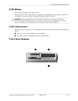
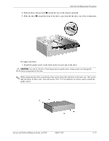
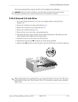
Removal and Replacement Procedures The system automatically recognizes the drive and reconfigures the workstation. Ä CAUTION: When servicing the workstation, ensure that cables are placed in their proper locations during the reassembly process. Improper cable placement can damage the workstation. 5.10.4 External 3.5-inch Drive 1. If you have locked the Smart Cover Lock, use Computer Setup to unlock the lock (Section 5.2). 2. Prepare the workstation for disassembly (Section 5.1). 3. Remove the workstation access panel (Section 5.5). 4. Remove the front bezel (Section 5.6). 5. Raise the Easy Access drive bay to the upright position. 6. Disconnect the audio, signal, and drive power cables from the drive. The other end of the cables should remain connected to the system board. 7. Return the Easy Access drive bay to the down position. 8. Push the drive release latch 1 toward the rear of the chassis and hold. 9. Slide the drive 2 toward the front of the drive cage, then lift the drive out of the workstation. ✎ When replacing the drive, transfer the four screws from the old drive to the new one. The screws take the place of drive rails. You will need a Torx T-15 screwdriver to remove and re-install the guide screws. Service and Technical Reference Guide, xw3100 338611-001 5-19
-
 1
1 -
2
-
3
-
4
-
5
-
6
-
7
-
8
-
9
-
10
-
11
-
12
-
13
-
14
-
15
-
16
-
17
-
18
-
19
-
20
-
21
-
22
-
23
-
24
-
25
-
26
-
27
-
28
-
29
-
30
-
31
-
32
-
33
-
34
-
35
-
36
-
37
-
38
-
39
-
40
-
41
-
42
-
43
-
44
-
45
-
46
-
47
-
48
-
49
-
50
-
51
-
52
-
53
-
54
-
55
-
56
-
57
-
58
-
59
-
60
-
61
-
62
-
63
-
64
-
65
-
66
-
67
-
68
-
69
-
70
-
71
-
 72
72 -
 73
73 -
 74
74 -
 75
75 -
 76
76 -
 77
77 -
 78
78 -
 79
79 -
 80
80 -
 81
81 -
 82
82 -
83
-
84
-
85
-
86
-
87
-
88
-
89
-
90
-
91
-
92
-
93
-
94
-
95
-
96
-
97
-
98
-
99
-
100
-
101
-
102
-
103
-
104
-
105
-
106
-
107
-
108
-
109
-
110
-
111
-
112
-
113
-
114
-
115
-
116
-
117
-
118
-
119
-
120
-
121
-
122
-
123
-
124
-
125
-
126
-
127
-
128
-
129
-
130
-
131
-
132
-
133
-
134
-
135
-
136
-
137
-
138
-
139
-
140
-
141
-
142
-
143
-
144
-
145
-
146
-
147
-
148
 |
 |