HP rp5800 Maintenance & Service Guide HP rp5800 Retail System - Page 102
Processor, CAUTION, - i7
 |
View all HP rp5800 manuals
Add to My Manuals
Save this manual to your list of manuals |
Page 102 highlights
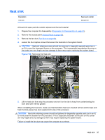
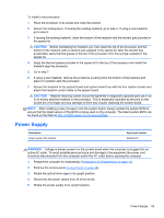
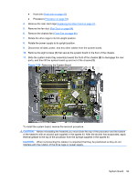
Processor Description Intel Core i7, 2600, 3.4 GHz, 8-MB L3 cache, 95W Intel Core i5, 2400, 3.1 GHz, 6-MB L3 cache, 95W Intel Core i3, 2120, 3.3 GHz, 3-MB L3 cache, 65W Intel Pentium Dual-Core, G850, 2.9-GHz, 3-MB L3 cache, 65W Spare part number 638632-001 638630-001 638412-001 655973-001 1. Prepare the computer for disassembly (Preparation for Disassembly on page 41). 2. Remove the access panel Access Panel on page 42). 3. Remove the fan duct (Fan Duct on page 84). 4. Remove the heat sink (Heat sink on page 91). 5. Rotate the locking lever to its full open position (1). 6. Raise and rotate the microprocessor retainer to its fully open position (2). 7. Carefully lift the processor from the socket (3). CAUTION: Do NOT handle the pins in the processor socket. These pins are very fragile and handling them could cause irreparable damage. Once pins are damaged it may be necessary to replace the system board. The heatsink must be installed within 24 hours of installing the processor to prevent damage to the processor's solder connections. Figure 7-57 Removing the Processor 92 Chapter 7 Removal and Replacement Procedures
-
 1
1 -
2
-
3
-
4
-
5
-
6
-
7
-
8
-
9
-
10
-
11
-
12
-
13
-
14
-
15
-
16
-
17
-
18
-
19
-
20
-
21
-
22
-
23
-
24
-
25
-
26
-
27
-
28
-
29
-
30
-
31
-
32
-
33
-
34
-
35
-
36
-
37
-
38
-
39
-
40
-
41
-
42
-
43
-
44
-
45
-
46
-
47
-
48
-
49
-
50
-
51
-
52
-
53
-
54
-
55
-
56
-
57
-
58
-
59
-
60
-
61
-
62
-
63
-
64
-
65
-
66
-
67
-
68
-
69
-
70
-
71
-
72
-
73
-
74
-
75
-
76
-
77
-
78
-
79
-
80
-
81
-
82
-
83
-
84
-
85
-
86
-
87
-
88
-
89
-
90
-
91
-
92
-
93
-
94
-
95
-
96
-
 97
97 -
 98
98 -
 99
99 -
 100
100 -
 101
101 -
 102
102 -
 103
103 -
 104
104 -
 105
105 -
 106
106 -
 107
107 -
108
-
109
-
110
-
111
-
112
-
113
-
114
-
115
-
116
-
117
-
118
-
119
-
120
-
121
-
122
-
123
-
124
-
125
-
126
-
127
-
128
-
129
-
130
-
131
-
132
-
133
-
134
-
135
-
136
-
137
-
138
-
139
-
140
-
141
-
142
-
143
-
144
-
145
-
146
-
147
-
148
-
149
-
150
-
151
-
152
-
153
-
154
-
155
-
156
-
157
-
158
-
159
-
160
-
161
-
162
-
163
-
164
-
165
-
166
-
167
-
168
-
169
-
170
-
171
-
172
-
173
-
174
-
175
-
176
-
177
-
178
-
179
-
180
-
181
-
182
-
183
-
184
-
185
 |
 |
