HP rp5800 Maintenance & Service Guide HP rp5800 Retail System - Page 105
CAUTION, Heat sink, on Processor, Replacing the Riser Card, Fan Duct, Front Fan
 |
View all HP rp5800 manuals
Add to My Manuals
Save this manual to your list of manuals |
Page 105 highlights
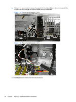
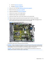
● Heat sink (Heat sink on page 91) ● Processor (Processor on page 92) 4. Remove the riser card cage Replacing the Riser Card on page 67. 5. Remove the fan duct (Fan Duct on page 84). 6. Remove the chassis fan (Front Fan on page 86). 7. Rotate the drive cage to its full upright position. 8. Rotate the power supply to its upright position. 9. Disconnect all data, power, and any other cables from the system board. 10. Remove the eight screws (1) that secure the system board to the floor of the chassis. 11. Slide the system board tray assembly toward the front of the chassis (2) to disengage the rear ports, and then lift the system board up and out of the chassis (3). Figure 7-59 Removing the System Board To install the system board, reverse the removal procedure. CAUTION: Before reinstalling the heatsink you must clean the top of the processor and the bottom of the heatsink with an alcohol pad supplied in the spares kit. After the alcohol has evaporated, apply thermal grease to the top of the processor from the syringe supplied in the spares kit. CAUTION: When reconnecting the cables it is important that they be positioned so they do not interfere with the rotation of the drive cage or power supply. System Board 95
-
 1
1 -
2
-
3
-
4
-
5
-
6
-
7
-
8
-
9
-
10
-
11
-
12
-
13
-
14
-
15
-
16
-
17
-
18
-
19
-
20
-
21
-
22
-
23
-
24
-
25
-
26
-
27
-
28
-
29
-
30
-
31
-
32
-
33
-
34
-
35
-
36
-
37
-
38
-
39
-
40
-
41
-
42
-
43
-
44
-
45
-
46
-
47
-
48
-
49
-
50
-
51
-
52
-
53
-
54
-
55
-
56
-
57
-
58
-
59
-
60
-
61
-
62
-
63
-
64
-
65
-
66
-
67
-
68
-
69
-
70
-
71
-
72
-
73
-
74
-
75
-
76
-
77
-
78
-
79
-
80
-
81
-
82
-
83
-
84
-
85
-
86
-
87
-
88
-
89
-
90
-
91
-
92
-
93
-
94
-
95
-
96
-
97
-
98
-
99
-
 100
100 -
 101
101 -
 102
102 -
 103
103 -
 104
104 -
 105
105 -
 106
106 -
 107
107 -
 108
108 -
 109
109 -
 110
110 -
111
-
112
-
113
-
114
-
115
-
116
-
117
-
118
-
119
-
120
-
121
-
122
-
123
-
124
-
125
-
126
-
127
-
128
-
129
-
130
-
131
-
132
-
133
-
134
-
135
-
136
-
137
-
138
-
139
-
140
-
141
-
142
-
143
-
144
-
145
-
146
-
147
-
148
-
149
-
150
-
151
-
152
-
153
-
154
-
155
-
156
-
157
-
158
-
159
-
160
-
161
-
162
-
163
-
164
-
165
-
166
-
167
-
168
-
169
-
170
-
171
-
172
-
173
-
174
-
175
-
176
-
177
-
178
-
179
-
180
-
181
-
182
-
183
-
184
-
185
 |
 |