HP rp5800 Maintenance & Service Guide HP rp5800 Retail System - Page 97
Front USB and Power Switch Assembly, Disconnecting the Front USB and Power Switch Cables
 |
View all HP rp5800 manuals
Add to My Manuals
Save this manual to your list of manuals |
Page 97 highlights
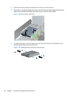
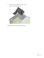
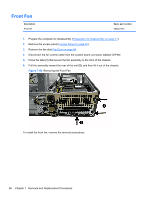
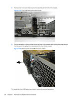
Front USB and Power Switch Assembly Description Front USB and power switch assembly Spare part number 655579-001 1. Prepare the computer for disassembly (Preparation for Disassembly on page 41). 2. Remove the access panel (Access Panel on page 42). 3. Remove the front bezel (Front Bezel on page 43). 4. Remove the fan duct Fan Duct on page 84. 5. Rotate the drive cage to its upright position. 6. Raise the drive cage to its upright position. 7. Disconnect the cables from the following system board connectors: ● FRONT USB (yellow) ● PB/LED (black) Figure 7-51 Disconnecting the Front USB and Power Switch Cables Front USB and Power Switch Assembly 87
-
 1
1 -
2
-
3
-
4
-
5
-
6
-
7
-
8
-
9
-
10
-
11
-
12
-
13
-
14
-
15
-
16
-
17
-
18
-
19
-
20
-
21
-
22
-
23
-
24
-
25
-
26
-
27
-
28
-
29
-
30
-
31
-
32
-
33
-
34
-
35
-
36
-
37
-
38
-
39
-
40
-
41
-
42
-
43
-
44
-
45
-
46
-
47
-
48
-
49
-
50
-
51
-
52
-
53
-
54
-
55
-
56
-
57
-
58
-
59
-
60
-
61
-
62
-
63
-
64
-
65
-
66
-
67
-
68
-
69
-
70
-
71
-
72
-
73
-
74
-
75
-
76
-
77
-
78
-
79
-
80
-
81
-
82
-
83
-
84
-
85
-
86
-
87
-
88
-
89
-
90
-
91
-
 92
92 -
 93
93 -
 94
94 -
 95
95 -
 96
96 -
 97
97 -
 98
98 -
 99
99 -
 100
100 -
 101
101 -
 102
102 -
103
-
104
-
105
-
106
-
107
-
108
-
109
-
110
-
111
-
112
-
113
-
114
-
115
-
116
-
117
-
118
-
119
-
120
-
121
-
122
-
123
-
124
-
125
-
126
-
127
-
128
-
129
-
130
-
131
-
132
-
133
-
134
-
135
-
136
-
137
-
138
-
139
-
140
-
141
-
142
-
143
-
144
-
145
-
146
-
147
-
148
-
149
-
150
-
151
-
152
-
153
-
154
-
155
-
156
-
157
-
158
-
159
-
160
-
161
-
162
-
163
-
164
-
165
-
166
-
167
-
168
-
169
-
170
-
171
-
172
-
173
-
174
-
175
-
176
-
177
-
178
-
179
-
180
-
181
-
182
-
183
-
184
-
185
 |
 |

Front USB and Power Switch Assembly
Description
Spare part number
Front USB and power switch assembly
655579-001
1.
Prepare the computer for disassembly (
Preparation for Disassembly
on page
41
).
2.
Remove the access panel (
Access Panel
on page
42
).
3.
Remove the front bezel (
Front Bezel
on page
43
).
4.
Remove the fan duct
Fan Duct
on page
84
.
5.
Rotate the drive cage to its upright position.
6.
Raise the drive cage to its upright position.
7.
Disconnect the cables from the following system board connectors:
●
FRONT USB (yellow)
●
PB/LED (black)
Figure 7-51
Disconnecting the Front USB and Power Switch Cables
Front USB and Power Switch Assembly
87