HP rp5800 Maintenance & Service Guide HP rp5800 Retail System - Page 113
When replacing the partition, note the following items.
 |
View all HP rp5800 manuals
Add to My Manuals
Save this manual to your list of manuals |
Page 113 highlights
5. After disengaging the partition from the rear of the chassis, lift the partition to disengage it from the front of the chassis (3), and then remove the partition from the computer (4). Figure 7-66 Removing the 50°C heat partition To install the 50°C heat partition, reverse the removal procedures. When replacing the partition, note the following items. A tab near the front on the side of the partition slides into a clip on the side of the drive cage. Figure 7-67 Installing the partition - attaching to side of optical drive cage A cap on the bottom of the partition fits over a screw on the heat sink. 50°C configuration components 103
-
 1
1 -
2
-
3
-
4
-
5
-
6
-
7
-
8
-
9
-
10
-
11
-
12
-
13
-
14
-
15
-
16
-
17
-
18
-
19
-
20
-
21
-
22
-
23
-
24
-
25
-
26
-
27
-
28
-
29
-
30
-
31
-
32
-
33
-
34
-
35
-
36
-
37
-
38
-
39
-
40
-
41
-
42
-
43
-
44
-
45
-
46
-
47
-
48
-
49
-
50
-
51
-
52
-
53
-
54
-
55
-
56
-
57
-
58
-
59
-
60
-
61
-
62
-
63
-
64
-
65
-
66
-
67
-
68
-
69
-
70
-
71
-
72
-
73
-
74
-
75
-
76
-
77
-
78
-
79
-
80
-
81
-
82
-
83
-
84
-
85
-
86
-
87
-
88
-
89
-
90
-
91
-
92
-
93
-
94
-
95
-
96
-
97
-
98
-
99
-
100
-
101
-
102
-
103
-
104
-
105
-
106
-
107
-
 108
108 -
 109
109 -
 110
110 -
 111
111 -
 112
112 -
 113
113 -
 114
114 -
 115
115 -
 116
116 -
 117
117 -
 118
118 -
119
-
120
-
121
-
122
-
123
-
124
-
125
-
126
-
127
-
128
-
129
-
130
-
131
-
132
-
133
-
134
-
135
-
136
-
137
-
138
-
139
-
140
-
141
-
142
-
143
-
144
-
145
-
146
-
147
-
148
-
149
-
150
-
151
-
152
-
153
-
154
-
155
-
156
-
157
-
158
-
159
-
160
-
161
-
162
-
163
-
164
-
165
-
166
-
167
-
168
-
169
-
170
-
171
-
172
-
173
-
174
-
175
-
176
-
177
-
178
-
179
-
180
-
181
-
182
-
183
-
184
-
185
 |
 |
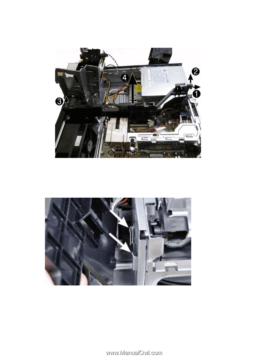
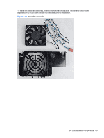
5.
After disengaging the partition from the rear of the chassis, lift the partition to disengage it from
the front of the chassis
(3)
, and then remove the partition from the computer
(4)
.
Figure 7-66
Removing the 50°C heat partition
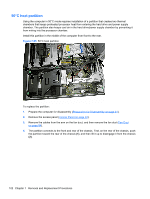
To install the 50°C heat partition, reverse the removal procedures.
When replacing the partition, note the following items.
A tab near the front on the side of the partition slides into a clip on the side of the drive cage.
Figure 7-67
Installing the partition – attaching to side of optical drive cage
A cap on the bottom of the partition fits over a screw on the heat sink.
50°C configuration components
103