HP rp5800 Maintenance & Service Guide HP rp5800 Retail System - Page 53
Front Bezel, Preparation for Disassembly, on Access Panel
 |
View all HP rp5800 manuals
Add to My Manuals
Save this manual to your list of manuals |
Page 53 highlights
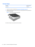
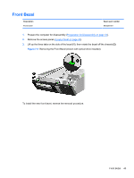
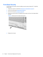
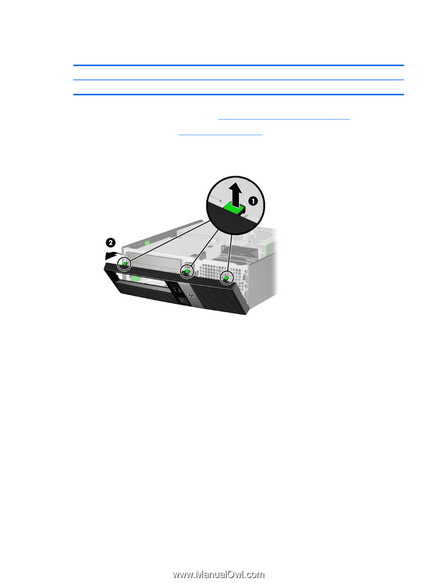
Front Bezel Description Front bezel Spare part number 653025-001 1. Prepare the computer for disassembly (Preparation for Disassembly on page 41). 2. Remove the access panel (Access Panel on page 42). 3. Lift up the three tabs on the side of the bezel (1), then rotate the bezel off the chassis (2). Figure 7-2 Removing the Front Bezel (shown with optical drive installed) To install the new front bezel, reverse the removal procedure. Front Bezel 43
-
 1
1 -
2
-
3
-
4
-
5
-
6
-
7
-
8
-
9
-
10
-
11
-
12
-
13
-
14
-
15
-
16
-
17
-
18
-
19
-
20
-
21
-
22
-
23
-
24
-
25
-
26
-
27
-
28
-
29
-
30
-
31
-
32
-
33
-
34
-
35
-
36
-
37
-
38
-
39
-
40
-
41
-
42
-
43
-
44
-
45
-
46
-
47
-
 48
48 -
 49
49 -
 50
50 -
 51
51 -
 52
52 -
 53
53 -
 54
54 -
 55
55 -
 56
56 -
 57
57 -
 58
58 -
59
-
60
-
61
-
62
-
63
-
64
-
65
-
66
-
67
-
68
-
69
-
70
-
71
-
72
-
73
-
74
-
75
-
76
-
77
-
78
-
79
-
80
-
81
-
82
-
83
-
84
-
85
-
86
-
87
-
88
-
89
-
90
-
91
-
92
-
93
-
94
-
95
-
96
-
97
-
98
-
99
-
100
-
101
-
102
-
103
-
104
-
105
-
106
-
107
-
108
-
109
-
110
-
111
-
112
-
113
-
114
-
115
-
116
-
117
-
118
-
119
-
120
-
121
-
122
-
123
-
124
-
125
-
126
-
127
-
128
-
129
-
130
-
131
-
132
-
133
-
134
-
135
-
136
-
137
-
138
-
139
-
140
-
141
-
142
-
143
-
144
-
145
-
146
-
147
-
148
-
149
-
150
-
151
-
152
-
153
-
154
-
155
-
156
-
157
-
158
-
159
-
160
-
161
-
162
-
163
-
164
-
165
-
166
-
167
-
168
-
169
-
170
-
171
-
172
-
173
-
174
-
175
-
176
-
177
-
178
-
179
-
180
-
181
-
182
-
183
-
184
-
185
 |
 |
Front Bezel
Description
Spare part number
Front bezel
653025-001
1.
Prepare the computer for disassembly (
Preparation for Disassembly
on page
41
).
2.
Remove the access panel (
Access Panel
on page
42
).
3.
Lift up the three tabs on the side of the bezel
(1)
, then rotate the bezel off the chassis
(2)
.
Figure 7-2
Removing the Front Bezel (shown with optical drive installed)
To install the new front bezel, reverse the removal procedure.
Front Bezel
43