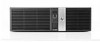
HP rp5800 Maintenance & Service Guide HP rp5800 Retail System - Page 8

Interpreting POST Diagnostic Front Panel LEDs and Audible Codes, Password Security and Resetting CMOS - cpu

Page 8 highlights

Power Supply ...93 System Board ...94 Battery ...96 50°C configuration components ...98 50°C radial fan ...99 50°C heat partition ...102 50°C rear expansion slot cover vents 106 50°C front bezel ...106 50°C heat sink ...106 Appendix A Connector Pin Assignments ...108 Keyboard ...108 Mouse ...108 Ethernet RJ-45 ...109 Parallel Interface ...109 Serial Interface, Powered and Non-Powered 110 USB ...110 Microphone ...110 Headphone ...110 Line-in Audio ...111 Line-out Audio ...111 Monitor ...111 6-Pin Power (for CPU) ...112 SATA Data and Power ...112 PCI Express, Pin A ...113 PCI Express, Pin B ...114 DVI Connector ...115 Appendix B Power Cord Set Requirements 116 General Requirements ...116 Japanese Power Cord Requirements 116 Country-Specific Requirements ...117 Appendix C POST Error Messages ...118 Power-On Self-Test (POST) ...118 POST Numeric Codes and Text Messages 119 Interpreting POST Diagnostic Front Panel LEDs and Audible Codes 125 Appendix D Password Security and Resetting CMOS 129 Resetting the Password Jumper ...130 viii

  • 1
  • 2
  • 3
  • 4
  • 5
  • 6
  • 7
  • 8
  • 9
  • 10
  • 11
  • 12
  • 13
  • 14
  • 15
  • 16
  • 17
  • 18
  • 19
  • 20
  • 21
  • 22
  • 23
  • 24
  • 25
  • 26
  • 27
  • 28
  • 29
  • 30
  • 31
  • 32
  • 33
  • 34
  • 35
  • 36
  • 37
  • 38
  • 39
  • 40
  • 41
  • 42
  • 43
  • 44
  • 45
  • 46
  • 47
  • 48
  • 49
  • 50
  • 51
  • 52
  • 53
  • 54
  • 55
  • 56
  • 57
  • 58
  • 59
  • 60
  • 61
  • 62
  • 63
  • 64
  • 65
  • 66
  • 67
  • 68
  • 69
  • 70
  • 71
  • 72
  • 73
  • 74
  • 75
  • 76
  • 77
  • 78
  • 79
  • 80
  • 81
  • 82
  • 83
  • 84
  • 85
  • 86
  • 87
  • 88
  • 89
  • 90
  • 91
  • 92
  • 93
  • 94
  • 95
  • 96
  • 97
  • 98
  • 99
  • 100
  • 101
  • 102
  • 103
  • 104
  • 105
  • 106
  • 107
  • 108
  • 109
  • 110
  • 111
  • 112
  • 113
  • 114
  • 115
  • 116
  • 117
  • 118
  • 119
  • 120
  • 121
  • 122
  • 123
  • 124
  • 125
  • 126
  • 127
  • 128
  • 129
  • 130
  • 131
  • 132
  • 133
  • 134
  • 135
  • 136
  • 137
  • 138
  • 139
  • 140
  • 141
  • 142
  • 143
  • 144
  • 145
  • 146
  • 147
  • 148
  • 149
  • 150
  • 151
  • 152
  • 153
  • 154
  • 155
  • 156
  • 157
  • 158
  • 159
  • 160
  • 161
  • 162
  • 163
  • 164
  • 165
  • 166
  • 167
  • 168
  • 169
  • 170
  • 171
  • 172
  • 173
  • 174
  • 175
  • 176
  • 177
  • 178
  • 179
  • 180
  • 181
  • 182
  • 183
  • 184
  • 185

Power Supply
.....................................................................................................................................
93
System Board
.....................................................................................................................................
94
Battery
................................................................................................................................................
96
50°C configuration components
.........................................................................................................
98
50°C radial fan
...................................................................................................................
99
50°C heat partition
...........................................................................................................
102
50°C rear expansion slot cover vents
..............................................................................
106
50°C front bezel
...............................................................................................................
106
50°C heat sink
.................................................................................................................
106
Appendix A
Connector Pin Assignments
....................................................................................................
108
Keyboard
..........................................................................................................................................
108
Mouse
...............................................................................................................................................
108
Ethernet RJ-45
.................................................................................................................................
109
Parallel Interface
..............................................................................................................................
109
Serial Interface, Powered and Non-Powered
...................................................................................
110
USB
..................................................................................................................................................
110
Microphone
.......................................................................................................................................
110
Headphone
.......................................................................................................................................
110
Line-in Audio
....................................................................................................................................
111
Line-out Audio
..................................................................................................................................
111
Monitor
.............................................................................................................................................
111
6-Pin Power (for CPU)
......................................................................................................................
112
SATA Data and Power
.....................................................................................................................
112
PCI Express, Pin A
...........................................................................................................................
113
PCI Express, Pin B
...........................................................................................................................
114
DVI Connector
..................................................................................................................................
115
Appendix B
Power Cord Set Requirements
................................................................................................
116
General Requirements
.....................................................................................................................
116
Japanese Power Cord Requirements
..............................................................................................
116
Country-Specific Requirements
........................................................................................................
117
Appendix C
POST Error Messages
..............................................................................................................
118
Power-On Self-Test (POST)
.............................................................................................................
118
POST Numeric Codes and Text Messages
.....................................................................................
119
Interpreting POST Diagnostic Front Panel LEDs and Audible Codes
..............................................
125
Appendix D
Password Security and Resetting CMOS
...............................................................................
129
Resetting the Password Jumper
......................................................................................................
130
viii