HP rp5800 Maintenance & Service Guide HP rp5800 Retail System - Page 104
System Board, CAUTION
 |
View all HP rp5800 manuals
Add to My Manuals
Save this manual to your list of manuals |
Page 104 highlights
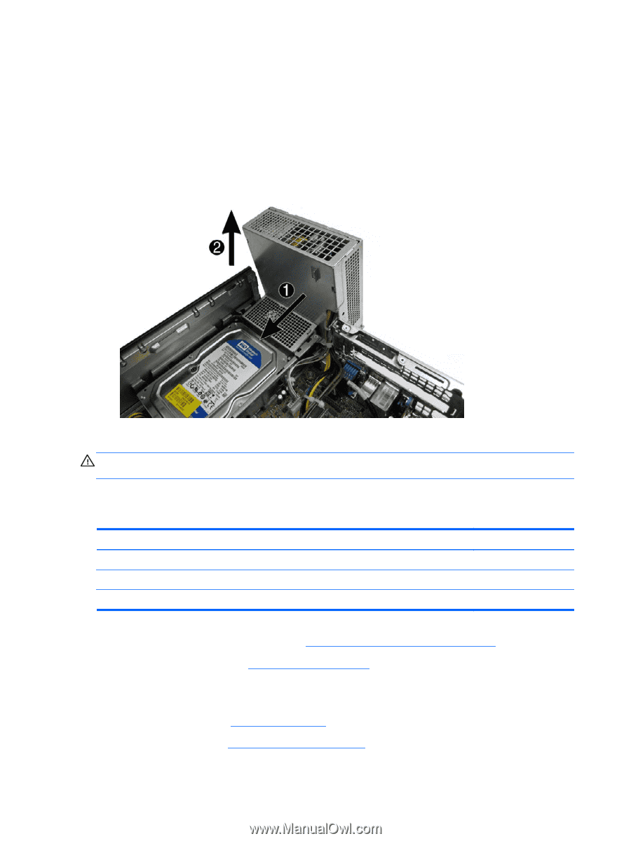
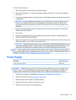
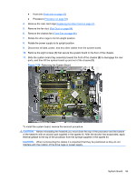
6. Disconnect the power cables from the following system board connectors: ● PWRCMD ● PWRCPU ● PWR 7. Pull the power supply forward (1) until the posts on the power supply move forward in the power supply bracket, and then lift the power supply straight up and out of the chassis (2). Figure 7-58 Removing the Power Supply To install the power supply, reverse the removal procedure. CAUTION: When installing the power supply cables, make sure they are properly positioned so they are not cut by the drive cage and are not pinched by the rotating power supply. System Board Description For use in 8200 Elite Series models: System board, includes Trusted Platform Module (TPM) (includes thermal material) System board, does not include Trusted Platform Module (TPM) Spare part number 655580-001 628930-001 1. Prepare the computer for disassembly (Preparation for Disassembly on page 41). 2. Remove the access panel (Access Panel on page 42). 3. When replacing the system board, make sure the following components are removed from the defective system board and installed on the replacement system board: ● Memory modules (Memory on page 50) ● Expansion cards (Expansion Cards on page 54) 94 Chapter 7 Removal and Replacement Procedures
-
 1
1 -
2
-
3
-
4
-
5
-
6
-
7
-
8
-
9
-
10
-
11
-
12
-
13
-
14
-
15
-
16
-
17
-
18
-
19
-
20
-
21
-
22
-
23
-
24
-
25
-
26
-
27
-
28
-
29
-
30
-
31
-
32
-
33
-
34
-
35
-
36
-
37
-
38
-
39
-
40
-
41
-
42
-
43
-
44
-
45
-
46
-
47
-
48
-
49
-
50
-
51
-
52
-
53
-
54
-
55
-
56
-
57
-
58
-
59
-
60
-
61
-
62
-
63
-
64
-
65
-
66
-
67
-
68
-
69
-
70
-
71
-
72
-
73
-
74
-
75
-
76
-
77
-
78
-
79
-
80
-
81
-
82
-
83
-
84
-
85
-
86
-
87
-
88
-
89
-
90
-
91
-
92
-
93
-
94
-
95
-
96
-
97
-
98
-
 99
99 -
 100
100 -
 101
101 -
 102
102 -
 103
103 -
 104
104 -
 105
105 -
 106
106 -
 107
107 -
 108
108 -
 109
109 -
110
-
111
-
112
-
113
-
114
-
115
-
116
-
117
-
118
-
119
-
120
-
121
-
122
-
123
-
124
-
125
-
126
-
127
-
128
-
129
-
130
-
131
-
132
-
133
-
134
-
135
-
136
-
137
-
138
-
139
-
140
-
141
-
142
-
143
-
144
-
145
-
146
-
147
-
148
-
149
-
150
-
151
-
152
-
153
-
154
-
155
-
156
-
157
-
158
-
159
-
160
-
161
-
162
-
163
-
164
-
165
-
166
-
167
-
168
-
169
-
170
-
171
-
172
-
173
-
174
-
175
-
176
-
177
-
178
-
179
-
180
-
181
-
182
-
183
-
184
-
185
 |
 |