HP rp5800 Maintenance & Service Guide HP rp5800 Retail System - Page 71
Connecting the 12-volt Powered USB Cable, Closing the Expansion Card Retention Latch
 |
View all HP rp5800 manuals
Add to My Manuals
Save this manual to your list of manuals |
Page 71 highlights
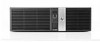
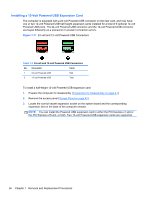
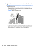
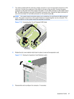
7. The cable included with the card has a single connector on one end and dual connectors on the other end. Connect the single end of the cable to the rear of the card (1). Connect the green connector on the other end of the cable to the green 12-volt USB connector on the system board (2). The cable will plug on one side of the green connector only. Connect the black connector to one of the two black 12-volt USB connectors on the system board (3). NOTE: The system board connectors allow you to install two 12-volt Powered USB expansion cards. The green connectors on the system board are coupled together as one connector. The black connectors on the system board are separate connectors. Figure 7-16 Connecting the 12-volt Powered USB Cable 8. Rotate the slot cover retention latch back in place to secure the expansion card. Figure 7-17 Closing the Expansion Card Retention Latch 9. Reassemble and reconfigure the computer, if necessary. Expansion Cards 61
-
 1
1 -
2
-
3
-
4
-
5
-
6
-
7
-
8
-
9
-
10
-
11
-
12
-
13
-
14
-
15
-
16
-
17
-
18
-
19
-
20
-
21
-
22
-
23
-
24
-
25
-
26
-
27
-
28
-
29
-
30
-
31
-
32
-
33
-
34
-
35
-
36
-
37
-
38
-
39
-
40
-
41
-
42
-
43
-
44
-
45
-
46
-
47
-
48
-
49
-
50
-
51
-
52
-
53
-
54
-
55
-
56
-
57
-
58
-
59
-
60
-
61
-
62
-
63
-
64
-
65
-
 66
66 -
 67
67 -
 68
68 -
 69
69 -
 70
70 -
 71
71 -
 72
72 -
 73
73 -
 74
74 -
 75
75 -
 76
76 -
77
-
78
-
79
-
80
-
81
-
82
-
83
-
84
-
85
-
86
-
87
-
88
-
89
-
90
-
91
-
92
-
93
-
94
-
95
-
96
-
97
-
98
-
99
-
100
-
101
-
102
-
103
-
104
-
105
-
106
-
107
-
108
-
109
-
110
-
111
-
112
-
113
-
114
-
115
-
116
-
117
-
118
-
119
-
120
-
121
-
122
-
123
-
124
-
125
-
126
-
127
-
128
-
129
-
130
-
131
-
132
-
133
-
134
-
135
-
136
-
137
-
138
-
139
-
140
-
141
-
142
-
143
-
144
-
145
-
146
-
147
-
148
-
149
-
150
-
151
-
152
-
153
-
154
-
155
-
156
-
157
-
158
-
159
-
160
-
161
-
162
-
163
-
164
-
165
-
166
-
167
-
168
-
169
-
170
-
171
-
172
-
173
-
174
-
175
-
176
-
177
-
178
-
179
-
180
-
181
-
182
-
183
-
184
-
185
 |
 |