HP rp5800 Maintenance & Service Guide HP rp5800 Retail System - Page 84
Installing and Removing Drives
 |
View all HP rp5800 manuals
Add to My Manuals
Save this manual to your list of manuals |
Page 84 highlights
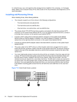
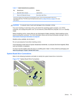
To verify the type, size, and capacity of the storage devices installed in the computer, run Computer Setup. Refer to the Computer Setup (F10) Utility Guide on the Documentation and Diagnostics CD for more information. Installing and Removing Drives When installing drives, follow these guidelines: ● The computer supports up to three drives in the following configurations: ◦ Two hard drives and one optical drive ◦ Two hard drives and one eSATA drive ◦ One hard drive, one optical drive, and one eSATA drive ● The primary Serial ATA (SATA) hard drive must be connected to the dark blue primary SATA connector on the system board labeled SATA0. If you are adding a second hard drive, connect it to the light blue connector on the system board labeled SATA1. ● Connect a SATA optical drive to the black eSATA connector on the system board labeled SATA2 unless an eSATA adapter is installed. If an eSATA adapter is installed, connect the optical drive to the light blue SATA connector on the system board labeled SATA1. ● Connect an optional eSATA adapter cable to the black eSATA connector on the system board labeled SATA2. ● The power cable for the SATA drives is a three-headed cable that is plugged into the system board with the first connector routed to the rear of the primary hard drive, the second connector routed to the rear of the secondary hard drive, and the third connector routed to the rear of the optical drive. ● You must install guide screws to ensure the drive will line up correctly in the drive cage and lock in place. HP has provided extra guide screws for the drive bays (five 6-32 standard screws and four M3 metric screws), installed in the front of the chassis, under the front bezel. The 6-32 standard screws are required for a secondary hard drive. The M3 metric screws are required for an optical drive. The HP-supplied metric screws are black and the HP-supplied standard screws are silver. If you are replacing the primary hard drive, you must remove the four silver and blue 6-32 isolation mounting guide screws from the old hard drive and install them in the new hard drive. Figure 7-36 Extra Guide Screw Locations 74 Chapter 7 Removal and Replacement Procedures
-
 1
1 -
2
-
3
-
4
-
5
-
6
-
7
-
8
-
9
-
10
-
11
-
12
-
13
-
14
-
15
-
16
-
17
-
18
-
19
-
20
-
21
-
22
-
23
-
24
-
25
-
26
-
27
-
28
-
29
-
30
-
31
-
32
-
33
-
34
-
35
-
36
-
37
-
38
-
39
-
40
-
41
-
42
-
43
-
44
-
45
-
46
-
47
-
48
-
49
-
50
-
51
-
52
-
53
-
54
-
55
-
56
-
57
-
58
-
59
-
60
-
61
-
62
-
63
-
64
-
65
-
66
-
67
-
68
-
69
-
70
-
71
-
72
-
73
-
74
-
75
-
76
-
77
-
78
-
 79
79 -
 80
80 -
 81
81 -
 82
82 -
 83
83 -
 84
84 -
 85
85 -
 86
86 -
 87
87 -
 88
88 -
 89
89 -
90
-
91
-
92
-
93
-
94
-
95
-
96
-
97
-
98
-
99
-
100
-
101
-
102
-
103
-
104
-
105
-
106
-
107
-
108
-
109
-
110
-
111
-
112
-
113
-
114
-
115
-
116
-
117
-
118
-
119
-
120
-
121
-
122
-
123
-
124
-
125
-
126
-
127
-
128
-
129
-
130
-
131
-
132
-
133
-
134
-
135
-
136
-
137
-
138
-
139
-
140
-
141
-
142
-
143
-
144
-
145
-
146
-
147
-
148
-
149
-
150
-
151
-
152
-
153
-
154
-
155
-
156
-
157
-
158
-
159
-
160
-
161
-
162
-
163
-
164
-
165
-
166
-
167
-
168
-
169
-
170
-
171
-
172
-
173
-
174
-
175
-
176
-
177
-
178
-
179
-
180
-
181
-
182
-
183
-
184
-
185
 |
 |
