HP rp5800 Maintenance & Service Guide HP rp5800 Retail System - Page 88
CAUTION, Installing the Optical Drive
 |
View all HP rp5800 manuals
Add to My Manuals
Save this manual to your list of manuals |
Page 88 highlights
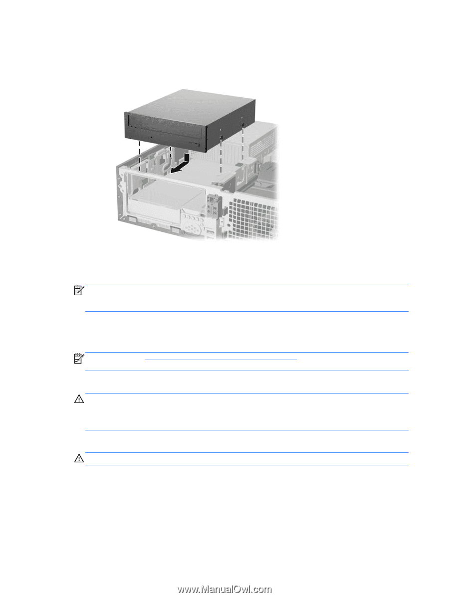
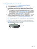
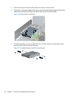
5. Position the guide screws on the drive into the J-slots in the drive bay. Then slide the drive toward the front of the computer until it locks into place. Figure 7-40 Installing the Optical Drive 6. Rotate the drive cage to its upright position. 7. Connect the power cable and data cable to the rear of the optical drive. NOTE: The power cable for the optical drive is a three-headed cable that is routed from the system board to the primary hard drive, then to the secondary hard drive, then to the rear of the optical drive. 8. Connect the SATA data cable to the black eSATA connector on the system board labeled SATA2 unless an eSATA adapter is installed. If an eSATA adapter is installed, connect the SATA data cable to the light blue SATA connector on the system board labeled SATA1. NOTE: Refer to System Board Drive Connections on page 75 for an illustration of the system board drive connectors. 9. Route the data cable through the cable guides. CAUTION: There are two cable guides that keep the data cable from being pinched by the drive cage when raising or lowering it. One is located on the bottom side of the drive cage. The other is located on the chassis frame under the drive cage. Ensure that the data cable is routed through these guides. 10. Rotate the drive cage back down to its normal position. CAUTION: Be careful not to pinch any cables or wires when rotating the drive cage down. 11. Reassemble the computer. 78 Chapter 7 Removal and Replacement Procedures
-
 1
1 -
2
-
3
-
4
-
5
-
6
-
7
-
8
-
9
-
10
-
11
-
12
-
13
-
14
-
15
-
16
-
17
-
18
-
19
-
20
-
21
-
22
-
23
-
24
-
25
-
26
-
27
-
28
-
29
-
30
-
31
-
32
-
33
-
34
-
35
-
36
-
37
-
38
-
39
-
40
-
41
-
42
-
43
-
44
-
45
-
46
-
47
-
48
-
49
-
50
-
51
-
52
-
53
-
54
-
55
-
56
-
57
-
58
-
59
-
60
-
61
-
62
-
63
-
64
-
65
-
66
-
67
-
68
-
69
-
70
-
71
-
72
-
73
-
74
-
75
-
76
-
77
-
78
-
79
-
80
-
81
-
82
-
 83
83 -
 84
84 -
 85
85 -
 86
86 -
 87
87 -
 88
88 -
 89
89 -
 90
90 -
 91
91 -
 92
92 -
 93
93 -
94
-
95
-
96
-
97
-
98
-
99
-
100
-
101
-
102
-
103
-
104
-
105
-
106
-
107
-
108
-
109
-
110
-
111
-
112
-
113
-
114
-
115
-
116
-
117
-
118
-
119
-
120
-
121
-
122
-
123
-
124
-
125
-
126
-
127
-
128
-
129
-
130
-
131
-
132
-
133
-
134
-
135
-
136
-
137
-
138
-
139
-
140
-
141
-
142
-
143
-
144
-
145
-
146
-
147
-
148
-
149
-
150
-
151
-
152
-
153
-
154
-
155
-
156
-
157
-
158
-
159
-
160
-
161
-
162
-
163
-
164
-
165
-
166
-
167
-
168
-
169
-
170
-
171
-
172
-
173
-
174
-
175
-
176
-
177
-
178
-
179
-
180
-
181
-
182
-
183
-
184
-
185
 |
 |