HP rp5800 Maintenance & Service Guide HP rp5800 Retail System - Page 86
Removing a 5.25-inch Optical Drive from a Drive Bay, CAUTION,
 |
View all HP rp5800 manuals
Add to My Manuals
Save this manual to your list of manuals |
Page 86 highlights
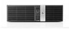
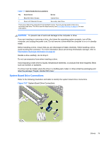
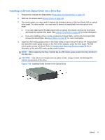
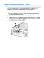
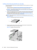
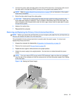
Table 7-8 System Board Drive Connections No. System Board Connector System Board Label 1 SATA0 SATA0 2 SATA1 SATA1 Color dark blue light blue 3 eSATA SATA2 black Device Primary Hard Drive Secondary Hard Drive or Optical Drive if an eSATA Adapter is present eSATA Adapter or Optical Drive Removing a 5.25-inch Optical Drive from a Drive Bay CAUTION: All removable media should be taken out of a drive before removing the drive from the computer. 1. Prepare the computer for disassembly (Preparation for Disassembly on page 41). 2. Remove the access panel (Access Panel on page 42). 3. Remove the front bezel (Front Bezel on page 43). 4. Rotate the drive cage to its upright position. 5. Disconnect the power cable and data cable from the rear of the optical drive. CAUTION: When removing the cables, pull the tab or connector instead of the cable itself to avoid damaging the cable. 6. Rotate the drive cage back down to its normal position. CAUTION: Be careful not to pinch any cables or wires when rotating the drive cage down. 7. Press down on the green drive retainer button located on the left side of the drive to disengage the drive from the drive cage (1). While pressing the drive retainer button, slide the drive back until it stops, then lift it up and out of the drive cage (2). Figure 7-38 Removing the 5.25-inch Drive 76 Chapter 7 Removal and Replacement Procedures
-
 1
1 -
2
-
3
-
4
-
5
-
6
-
7
-
8
-
9
-
10
-
11
-
12
-
13
-
14
-
15
-
16
-
17
-
18
-
19
-
20
-
21
-
22
-
23
-
24
-
25
-
26
-
27
-
28
-
29
-
30
-
31
-
32
-
33
-
34
-
35
-
36
-
37
-
38
-
39
-
40
-
41
-
42
-
43
-
44
-
45
-
46
-
47
-
48
-
49
-
50
-
51
-
52
-
53
-
54
-
55
-
56
-
57
-
58
-
59
-
60
-
61
-
62
-
63
-
64
-
65
-
66
-
67
-
68
-
69
-
70
-
71
-
72
-
73
-
74
-
75
-
76
-
77
-
78
-
79
-
80
-
 81
81 -
 82
82 -
 83
83 -
 84
84 -
 85
85 -
 86
86 -
 87
87 -
 88
88 -
 89
89 -
 90
90 -
 91
91 -
92
-
93
-
94
-
95
-
96
-
97
-
98
-
99
-
100
-
101
-
102
-
103
-
104
-
105
-
106
-
107
-
108
-
109
-
110
-
111
-
112
-
113
-
114
-
115
-
116
-
117
-
118
-
119
-
120
-
121
-
122
-
123
-
124
-
125
-
126
-
127
-
128
-
129
-
130
-
131
-
132
-
133
-
134
-
135
-
136
-
137
-
138
-
139
-
140
-
141
-
142
-
143
-
144
-
145
-
146
-
147
-
148
-
149
-
150
-
151
-
152
-
153
-
154
-
155
-
156
-
157
-
158
-
159
-
160
-
161
-
162
-
163
-
164
-
165
-
166
-
167
-
168
-
169
-
170
-
171
-
172
-
173
-
174
-
175
-
176
-
177
-
178
-
179
-
180
-
181
-
182
-
183
-
184
-
185
 |
 |