HP rp5800 Maintenance & Service Guide HP rp5800 Retail System - Page 98
Removing the front USB and power switch
 |
View all HP rp5800 manuals
Add to My Manuals
Save this manual to your list of manuals |
Page 98 highlights
8. Remove the Torx screw that secures the assembly to the front of the chassis. Figure 7-52 Front USB and power switch screw 9. Pull the assembly out through the hole in the front of the chassis while guiding the wires through the hole under the optical drive bracket and the front of the chassis. Figure 7-53 Removing the front USB and power switch To reinstall the front USB and power switch, reverse the removal procedure. 88 Chapter 7 Removal and Replacement Procedures
-
 1
1 -
2
-
3
-
4
-
5
-
6
-
7
-
8
-
9
-
10
-
11
-
12
-
13
-
14
-
15
-
16
-
17
-
18
-
19
-
20
-
21
-
22
-
23
-
24
-
25
-
26
-
27
-
28
-
29
-
30
-
31
-
32
-
33
-
34
-
35
-
36
-
37
-
38
-
39
-
40
-
41
-
42
-
43
-
44
-
45
-
46
-
47
-
48
-
49
-
50
-
51
-
52
-
53
-
54
-
55
-
56
-
57
-
58
-
59
-
60
-
61
-
62
-
63
-
64
-
65
-
66
-
67
-
68
-
69
-
70
-
71
-
72
-
73
-
74
-
75
-
76
-
77
-
78
-
79
-
80
-
81
-
82
-
83
-
84
-
85
-
86
-
87
-
88
-
89
-
90
-
91
-
92
-
 93
93 -
 94
94 -
 95
95 -
 96
96 -
 97
97 -
 98
98 -
 99
99 -
 100
100 -
 101
101 -
 102
102 -
 103
103 -
104
-
105
-
106
-
107
-
108
-
109
-
110
-
111
-
112
-
113
-
114
-
115
-
116
-
117
-
118
-
119
-
120
-
121
-
122
-
123
-
124
-
125
-
126
-
127
-
128
-
129
-
130
-
131
-
132
-
133
-
134
-
135
-
136
-
137
-
138
-
139
-
140
-
141
-
142
-
143
-
144
-
145
-
146
-
147
-
148
-
149
-
150
-
151
-
152
-
153
-
154
-
155
-
156
-
157
-
158
-
159
-
160
-
161
-
162
-
163
-
164
-
165
-
166
-
167
-
168
-
169
-
170
-
171
-
172
-
173
-
174
-
175
-
176
-
177
-
178
-
179
-
180
-
181
-
182
-
183
-
184
-
185
 |
 |
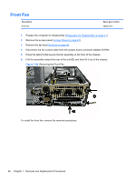
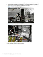
8.
Remove the Torx screw that secures the assembly to the front of the chassis.
Figure 7-52
Front USB and power switch screw
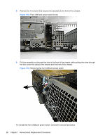
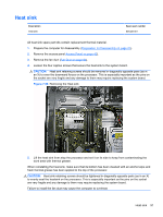
9.
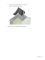
Pull the assembly out through the hole in the front of the chassis while guiding the wires through
the hole under the optical drive bracket and the front of the chassis.
Figure 7-53
Removing the front USB and power switch
To reinstall the front USB and power switch, reverse the removal procedure.
88
Chapter 7
Removal and Replacement Procedures