HP rp5800 Maintenance & Service Guide HP rp5800 Retail System - Page 87
Installing a 5.25-inch Optical Drive into a Drive Bay, CAUTION,
 |
View all HP rp5800 manuals
Add to My Manuals
Save this manual to your list of manuals |
Page 87 highlights
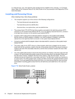
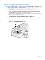
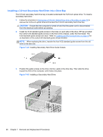
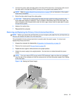
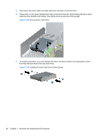
Installing a 5.25-inch Optical Drive into a Drive Bay 1. Prepare the computer for disassembly (Preparation for Disassembly on page 41). 2. Remove the access panel (Access Panel on page 42). 3. On some models, you may need to replace the driveless section of the front bezel with an optical drive bezel. On other models, you may need to remove a bezel blank from the optical drive bezel. ● If you are replacing the driveless bezel with an optical drive bezel, remove the front bezel and install the optical drive bezel. See Optical Drive Bezel on page 46 for more information ● If you are installing a drive in a bay covered by a bezel blank, remove the front bezel then remove the bezel blank. See Bezel Blank on page 47 for more information. 4. Install four M3 metric guide screws in the lower holes on each side of the drive. HP has provided four extra M3 metric guide screws on the front of the chassis, under the front bezel. The M3 metric guide screws are black. Refer to Installing and Removing Drives on page 74 for an illustration of the extra M3 metric guide screws location. NOTE: When replacing the drive, transfer the four M3 metric guide screws from the old drive to the new one. CAUTION: Use only 5-mm long screws as guide screws. Longer screws can damage the internal components of the drive. Figure 7-39 Installing Guide Screws in the Optical Drive Drives 77
-
 1
1 -
2
-
3
-
4
-
5
-
6
-
7
-
8
-
9
-
10
-
11
-
12
-
13
-
14
-
15
-
16
-
17
-
18
-
19
-
20
-
21
-
22
-
23
-
24
-
25
-
26
-
27
-
28
-
29
-
30
-
31
-
32
-
33
-
34
-
35
-
36
-
37
-
38
-
39
-
40
-
41
-
42
-
43
-
44
-
45
-
46
-
47
-
48
-
49
-
50
-
51
-
52
-
53
-
54
-
55
-
56
-
57
-
58
-
59
-
60
-
61
-
62
-
63
-
64
-
65
-
66
-
67
-
68
-
69
-
70
-
71
-
72
-
73
-
74
-
75
-
76
-
77
-
78
-
79
-
80
-
81
-
 82
82 -
 83
83 -
 84
84 -
 85
85 -
 86
86 -
 87
87 -
 88
88 -
 89
89 -
 90
90 -
 91
91 -
 92
92 -
93
-
94
-
95
-
96
-
97
-
98
-
99
-
100
-
101
-
102
-
103
-
104
-
105
-
106
-
107
-
108
-
109
-
110
-
111
-
112
-
113
-
114
-
115
-
116
-
117
-
118
-
119
-
120
-
121
-
122
-
123
-
124
-
125
-
126
-
127
-
128
-
129
-
130
-
131
-
132
-
133
-
134
-
135
-
136
-
137
-
138
-
139
-
140
-
141
-
142
-
143
-
144
-
145
-
146
-
147
-
148
-
149
-
150
-
151
-
152
-
153
-
154
-
155
-
156
-
157
-
158
-
159
-
160
-
161
-
162
-
163
-
164
-
165
-
166
-
167
-
168
-
169
-
170
-
171
-
172
-
173
-
174
-
175
-
176
-
177
-
178
-
179
-
180
-
181
-
182
-
183
-
184
-
185
 |
 |
