D-Link DGS-3308FG Product Manual - Page 102
Layer 3 Multicasting
 |
UPC - 790069239373
View all D-Link DGS-3308FG manuals
Add to My Manuals
Save this manual to your list of manuals |
Page 102 highlights
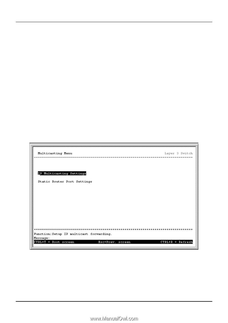
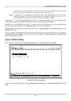
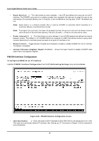
8-port Gigabit Ethernet Switch User's Guide port of the Layer 3 switch would not be able to receive UDP data streams at all of its ports unless the UDP multicast packets were all forwarded to the router port. Note: A router port will be dynamically configured when IGMP query packets, RIPv2 multicast, DVMRP multicast, PIM-DM multicast packets are detected flowing into a port. It is recommended that router ports be statically configured whenever possible. The Action:< > field can be toggled between Add/Modify and Delete using the space bar. To add a port to the static router port table, select Add/Modify and enter the VID of the VLAN the router port will belong to. Highlight the first field of Router Port (M/-):[ ]. Each port can be set individually as a router port by highlighting the port's entry using the arrow keys, and then toggling between M and - using the space bar. Highlight APPLY and press enter to make the changes current. Use Save Changes from the Main Menu to enter the changes into NV-RAM. To delete an entry, select Delete and enter the VID of the VLAN for which the router port table entry is to be deleted. Highlight APPLY and press Enter. The entry for the VLAN will be deleted. Use Save Changes from the Main Menu to enter the changes into NV-RAM. Layer 3 Multicasting With the Switch in IP Routing mode, highlight Multicasting from the Main Menu and press Enter. Figure 6-39. Multicasting Menu To set up IP multicasting on the Switch, highlight IP Multicast Settings from the Multicasting Menu and press Enter. 92
-
 1
1 -
2
-
3
-
4
-
5
-
6
-
7
-
8
-
9
-
10
-
11
-
12
-
13
-
14
-
15
-
16
-
17
-
18
-
19
-
20
-
21
-
22
-
23
-
24
-
25
-
26
-
27
-
28
-
29
-
30
-
31
-
32
-
33
-
34
-
35
-
36
-
37
-
38
-
39
-
40
-
41
-
42
-
43
-
44
-
45
-
46
-
47
-
48
-
49
-
50
-
51
-
52
-
53
-
54
-
55
-
56
-
57
-
58
-
59
-
60
-
61
-
62
-
63
-
64
-
65
-
66
-
67
-
68
-
69
-
70
-
71
-
72
-
73
-
74
-
75
-
76
-
77
-
78
-
79
-
80
-
81
-
82
-
83
-
84
-
85
-
86
-
87
-
88
-
89
-
90
-
91
-
92
-
93
-
94
-
95
-
96
-
 97
97 -
 98
98 -
 99
99 -
 100
100 -
 101
101 -
 102
102 -
 103
103 -
 104
104 -
 105
105 -
 106
106 -
 107
107 -
108
-
109
-
110
-
111
-
112
-
113
-
114
-
115
-
116
-
117
-
118
-
119
-
120
-
121
-
122
-
123
-
124
-
125
-
126
-
127
-
128
-
129
-
130
-
131
-
132
-
133
-
134
-
135
-
136
-
137
-
138
-
139
-
140
-
141
-
142
-
143
-
144
-
145
-
146
-
147
-
148
-
149
-
150
-
151
-
152
-
153
-
154
-
155
-
156
-
157
-
158
-
159
-
160
-
161
-
162
-
163
-
164
-
165
-
166
-
167
-
168
-
169
-
170
-
171
-
172
-
173
-
174
-
175
-
176
-
177
-
178
-
179
-
180
-
181
-
182
-
183
-
184
-
185
-
186
-
187
-
188
-
189
-
190
-
191
-
192
-
193
-
194
-
195
-
196
-
197
-
198
-
199
-
200
-
201
-
202
-
203
-
204
-
205
-
206
-
207
-
208
-
209
-
210
-
211
-
212
-
213
-
214
-
215
-
216
-
217
-
218
-
219
-
220
-
221
-
222
-
223
-
224
-
225
-
226
-
227
-
228
-
229
-
230
-
231
-
232
-
233
-
234
-
235
-
236
-
237
 |
 |