D-Link DGS-3308FG Product Manual - Page 78
Configuring the Switch's IP Address
 |
UPC - 790069239373
View all D-Link DGS-3308FG manuals
Add to My Manuals
Save this manual to your list of manuals |
Page 78 highlights
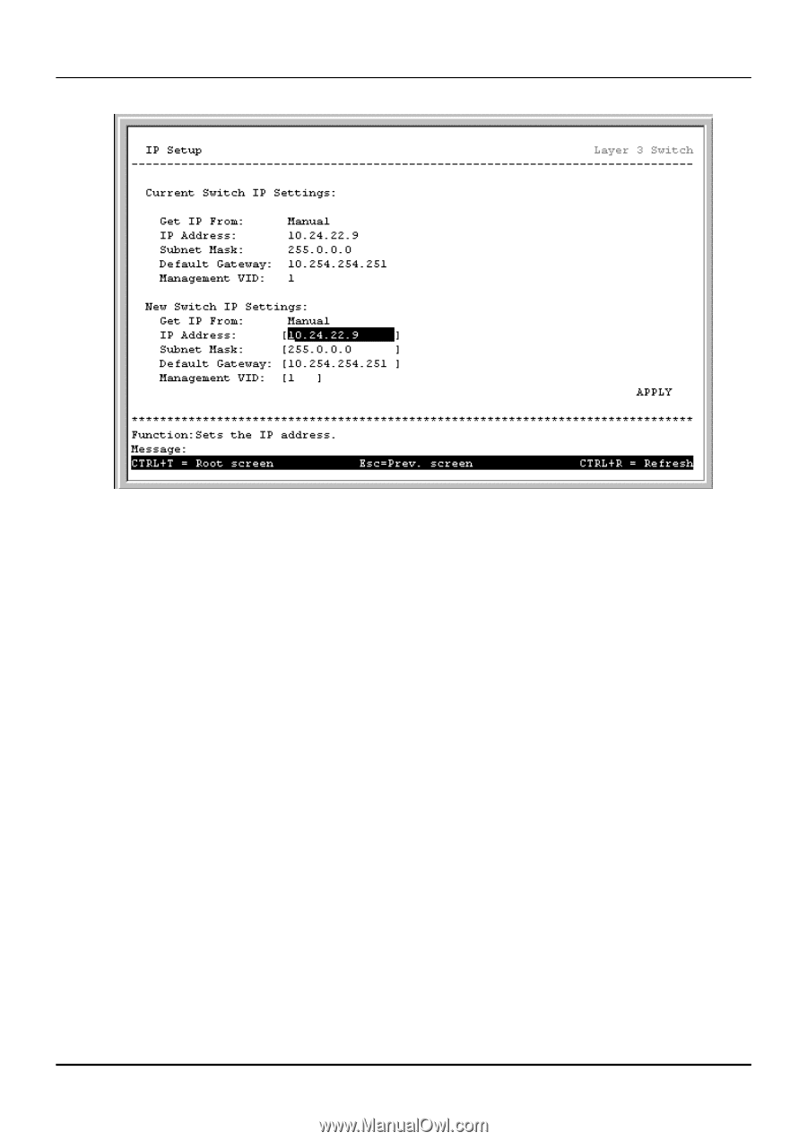
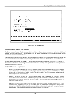
8-port Gigabit Ethernet Switch User's Guide Figure 6-13. IP Setup screen Configuring the Switch's IP Address The Switch needs to have an IP address assigned to it so that an In-Band network management system (e.g. Web-based Manager or Telnet) client can find it on the network. The IP Setup screen allows you to change the settings for this management interface used on the Switch. The fields listed under the Current Switch IP Settings heading are those that are currently being used by the Switch. The fields listed under the New Switch IP Settings heading are those that will be used after the Switch has been Rebooted. In Layer 2 mode, toggle the Get IP From: < > field using the space bar to choose from Manual, BOOTP, or DHCP. This selects how the Switch will be assigned an IP address on the next reboot (or startup). If the Switch is in Layer 3 mode, Manual is automatically assigned. The Get IP From: < > options are: • BOOTP - The Switch will send out a BOOTP broadcast request when it is powered up. The BOOTP protocol allows IP addresses, network masks, and default gateways to be assigned by a central BOOTP server. If this option is set, the Switch will first look for a BOOTP server to provide it with this information before using the default or previously entered settings. • DHCP - The Switch will send out a DHCP broadcast request when it is powered up. The DHCP protocol allows IP addresses, network masks, and default gateways to be assigned by a DHCP server. If this option is set, the Switch will first look for a DHCP server to provide it with this information before using the default or previously entered settings. • Manual - Allows the entry of an IP address, Subnet Mask, and a Default Gateway for the Switch. These fields should be of the form xxx.xxx.xxx.xxx, where each xxx is a number (represented in decimal form) between 0 and 255. This address should be a unique address on the network assigned for use by the Network Administrator. The fields which require entries under this option are as follows: 68
-
 1
1 -
2
-
3
-
4
-
5
-
6
-
7
-
8
-
9
-
10
-
11
-
12
-
13
-
14
-
15
-
16
-
17
-
18
-
19
-
20
-
21
-
22
-
23
-
24
-
25
-
26
-
27
-
28
-
29
-
30
-
31
-
32
-
33
-
34
-
35
-
36
-
37
-
38
-
39
-
40
-
41
-
42
-
43
-
44
-
45
-
46
-
47
-
48
-
49
-
50
-
51
-
52
-
53
-
54
-
55
-
56
-
57
-
58
-
59
-
60
-
61
-
62
-
63
-
64
-
65
-
66
-
67
-
68
-
69
-
70
-
71
-
72
-
 73
73 -
 74
74 -
 75
75 -
 76
76 -
 77
77 -
 78
78 -
 79
79 -
 80
80 -
 81
81 -
 82
82 -
 83
83 -
84
-
85
-
86
-
87
-
88
-
89
-
90
-
91
-
92
-
93
-
94
-
95
-
96
-
97
-
98
-
99
-
100
-
101
-
102
-
103
-
104
-
105
-
106
-
107
-
108
-
109
-
110
-
111
-
112
-
113
-
114
-
115
-
116
-
117
-
118
-
119
-
120
-
121
-
122
-
123
-
124
-
125
-
126
-
127
-
128
-
129
-
130
-
131
-
132
-
133
-
134
-
135
-
136
-
137
-
138
-
139
-
140
-
141
-
142
-
143
-
144
-
145
-
146
-
147
-
148
-
149
-
150
-
151
-
152
-
153
-
154
-
155
-
156
-
157
-
158
-
159
-
160
-
161
-
162
-
163
-
164
-
165
-
166
-
167
-
168
-
169
-
170
-
171
-
172
-
173
-
174
-
175
-
176
-
177
-
178
-
179
-
180
-
181
-
182
-
183
-
184
-
185
-
186
-
187
-
188
-
189
-
190
-
191
-
192
-
193
-
194
-
195
-
196
-
197
-
198
-
199
-
200
-
201
-
202
-
203
-
204
-
205
-
206
-
207
-
208
-
209
-
210
-
211
-
212
-
213
-
214
-
215
-
216
-
217
-
218
-
219
-
220
-
221
-
222
-
223
-
224
-
225
-
226
-
227
-
228
-
229
-
230
-
231
-
232
-
233
-
234
-
235
-
236
-
237
 |
 |