D-Link DGS-3308FG Product Manual - Page 37
Ingress Filtering, Layer 3-Based VLANs, VLANs in Layer 2 Only Mode, Setting up IP Interfaces
 |
UPC - 790069239373
View all D-Link DGS-3308FG manuals
Add to My Manuals
Save this manual to your list of manuals |
Page 37 highlights
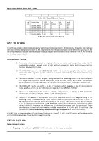
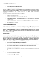
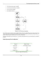
8-port Gigabit Ethernet Switch User's Guide Ingress Filtering A port on a switch where packets are flowing into the switch and VLAN decisions must be made is referred to as an ingress port. If ingress filtering is enabled for a port, the switch will examine the VLAN information in the packet header (if present) and decide whether or not to forward the packet. If the packet is tagged with VLAN information, the ingress port will first determine if the ingress port itself is a member of the tagged VLAN. If it is not, the packet will be dropped. If the ingress port is a member of the 802.1Q VLAN, the switch then determines if the destination port is a member of the 802.1Q VLAN. If it is not, the packet is dropped. If the destination port is a member of the 802.1Q VLAN, the packet is forwarded and the destination port transmits it to its attached network segment. If the packet is not tagged with VLAN information, the ingress port will tag the packet with its own PVID as a VID (if the port is a tagging port). The switch then determines if the destination port is a member of the same VLAN (has the same VID) as the ingress port. If it does not, the packet is dropped. If it has the same VID, the packet is forwarded and the destination port transmits it on its attached network segment. This process is referred to as ingress filtering and is used to conserve bandwidth within the switch by dropping packets that are not on the same VLAN as the ingress port at the point of reception. This eliminates the subsequent processing of packets that will just be dropped by the destination port. Layer 3-Based VLANs The DGS-3308 allows an IP subnet to be configured for each 802.1Q VLAN that exists on the switch. Even though a switch inspects a packet's IP address to determine VLAN membership, no route calculation is performed, the RIP or OSPF protocols are not employed, and packets traversing the switch are bridged using the Spanning Tree algorithm. A switch that implements layer 3 (or 'subnet') VLANs without performing any routing function between these VLANs is referred to as performing 'IP Switching'. IP switching does not allow packets to cross VLANs (in this case - IP subnets) without a network device performing a routing function between the VLANs (IP subnets). The DGS-3308 does not directly support IP switching, however it is possible to do the equivalent by assigning IP subnets to configured VLANs and then disabling the Routing Information Protocol (RIP). This will prevent packets from crossing IP subnets without going through an external router. VLANs in Layer 2 Only Mode The switch initially configures one VLAN, VID = 1, called the DEFAULT_VLAN. The factory default setting assigns all ports on the switch to the DEFAULT_VLAN. As new VLANs are configured, there respective member ports are removed from the DEFAULT_VLAN. If the DEFAULT_VLAN is reconfigured, all ports are again assigned to it. Ports that are not desired to be part of the DEFAULT_VLAN are removed during the configuration. Packets cannot cross VLANs if the switch is in Layer 2 Only mode.If a member of one VLAN wants to connect to another VLAN, the link must be through an external router. When the switch is in Layer 2 Only mode, 802.1Q VLANs are supported. Setting up IP Interfaces The Layer 3 switch allows ranges of IP addresses (OSI layer 3) to be assigned to VLANs (OSI layer 2). Each VLAN must be configured prior to setting up the corresponding IP interface. An IP addressing scheme must then be established, and implemented when the IP interfaces are set up on the switch. 27
-
 1
1 -
2
-
3
-
4
-
5
-
6
-
7
-
8
-
9
-
10
-
11
-
12
-
13
-
14
-
15
-
16
-
17
-
18
-
19
-
20
-
21
-
22
-
23
-
24
-
25
-
26
-
27
-
28
-
29
-
30
-
31
-
 32
32 -
 33
33 -
 34
34 -
 35
35 -
 36
36 -
 37
37 -
 38
38 -
 39
39 -
 40
40 -
 41
41 -
 42
42 -
43
-
44
-
45
-
46
-
47
-
48
-
49
-
50
-
51
-
52
-
53
-
54
-
55
-
56
-
57
-
58
-
59
-
60
-
61
-
62
-
63
-
64
-
65
-
66
-
67
-
68
-
69
-
70
-
71
-
72
-
73
-
74
-
75
-
76
-
77
-
78
-
79
-
80
-
81
-
82
-
83
-
84
-
85
-
86
-
87
-
88
-
89
-
90
-
91
-
92
-
93
-
94
-
95
-
96
-
97
-
98
-
99
-
100
-
101
-
102
-
103
-
104
-
105
-
106
-
107
-
108
-
109
-
110
-
111
-
112
-
113
-
114
-
115
-
116
-
117
-
118
-
119
-
120
-
121
-
122
-
123
-
124
-
125
-
126
-
127
-
128
-
129
-
130
-
131
-
132
-
133
-
134
-
135
-
136
-
137
-
138
-
139
-
140
-
141
-
142
-
143
-
144
-
145
-
146
-
147
-
148
-
149
-
150
-
151
-
152
-
153
-
154
-
155
-
156
-
157
-
158
-
159
-
160
-
161
-
162
-
163
-
164
-
165
-
166
-
167
-
168
-
169
-
170
-
171
-
172
-
173
-
174
-
175
-
176
-
177
-
178
-
179
-
180
-
181
-
182
-
183
-
184
-
185
-
186
-
187
-
188
-
189
-
190
-
191
-
192
-
193
-
194
-
195
-
196
-
197
-
198
-
199
-
200
-
201
-
202
-
203
-
204
-
205
-
206
-
207
-
208
-
209
-
210
-
211
-
212
-
213
-
214
-
215
-
216
-
217
-
218
-
219
-
220
-
221
-
222
-
223
-
224
-
225
-
226
-
227
-
228
-
229
-
230
-
231
-
232
-
233
-
234
-
235
-
236
-
237
 |
 |