D-Link DGS-3308FG Product Manual - Page 77
IP Setup
 |
UPC - 790069239373
View all D-Link DGS-3308FG manuals
Add to My Manuals
Save this manual to your list of manuals |
Page 77 highlights
8-port Gigabit Ethernet Switch User's Guide Figure 6-12. Power Supply and Cooling Fan Status screen IP Setup Some settings must be entered to allow the Switch to be managed from an SNMP-based Network Management System such as SNMP v1 or to be able to access the Switch using the Telnet protocol or the Web-based Manager. Please see the next chapter for Web-based network management information. The IP Setup menu lets you specify how the Switch will be assigned an IP address to allow it to be identified on the network. To setup the Switch for remote management: Highlight IP Setup from the Main Menu. The following screen appears: 67
-
 1
1 -
2
-
3
-
4
-
5
-
6
-
7
-
8
-
9
-
10
-
11
-
12
-
13
-
14
-
15
-
16
-
17
-
18
-
19
-
20
-
21
-
22
-
23
-
24
-
25
-
26
-
27
-
28
-
29
-
30
-
31
-
32
-
33
-
34
-
35
-
36
-
37
-
38
-
39
-
40
-
41
-
42
-
43
-
44
-
45
-
46
-
47
-
48
-
49
-
50
-
51
-
52
-
53
-
54
-
55
-
56
-
57
-
58
-
59
-
60
-
61
-
62
-
63
-
64
-
65
-
66
-
67
-
68
-
69
-
70
-
71
-
 72
72 -
 73
73 -
 74
74 -
 75
75 -
 76
76 -
 77
77 -
 78
78 -
 79
79 -
 80
80 -
 81
81 -
 82
82 -
83
-
84
-
85
-
86
-
87
-
88
-
89
-
90
-
91
-
92
-
93
-
94
-
95
-
96
-
97
-
98
-
99
-
100
-
101
-
102
-
103
-
104
-
105
-
106
-
107
-
108
-
109
-
110
-
111
-
112
-
113
-
114
-
115
-
116
-
117
-
118
-
119
-
120
-
121
-
122
-
123
-
124
-
125
-
126
-
127
-
128
-
129
-
130
-
131
-
132
-
133
-
134
-
135
-
136
-
137
-
138
-
139
-
140
-
141
-
142
-
143
-
144
-
145
-
146
-
147
-
148
-
149
-
150
-
151
-
152
-
153
-
154
-
155
-
156
-
157
-
158
-
159
-
160
-
161
-
162
-
163
-
164
-
165
-
166
-
167
-
168
-
169
-
170
-
171
-
172
-
173
-
174
-
175
-
176
-
177
-
178
-
179
-
180
-
181
-
182
-
183
-
184
-
185
-
186
-
187
-
188
-
189
-
190
-
191
-
192
-
193
-
194
-
195
-
196
-
197
-
198
-
199
-
200
-
201
-
202
-
203
-
204
-
205
-
206
-
207
-
208
-
209
-
210
-
211
-
212
-
213
-
214
-
215
-
216
-
217
-
218
-
219
-
220
-
221
-
222
-
223
-
224
-
225
-
226
-
227
-
228
-
229
-
230
-
231
-
232
-
233
-
234
-
235
-
236
-
237
 |
 |
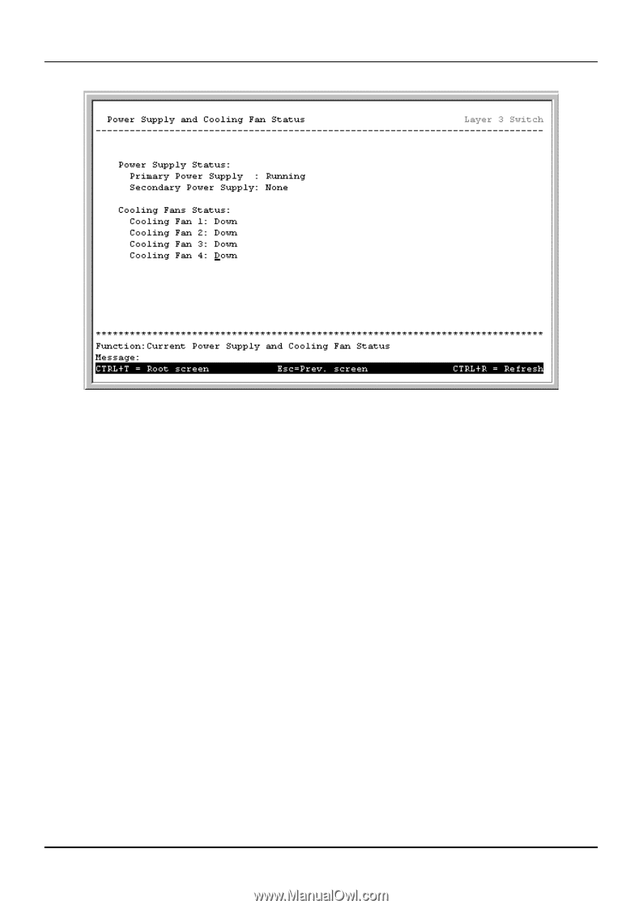
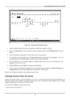
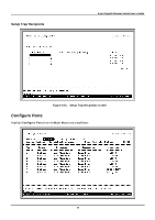
8-port Gigabit Ethernet Switch User’s Guide
67
Figure 6-12.
Power Supply and Cooling Fan Status screen
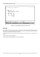
IP Setup
Some settings must be entered to allow the Switch to be managed from an SNMP-based Network Management System
such as SNMP v1 or to be able to access the Switch using the
Telnet
protocol or the Web-based Manager. Please see the
next chapter for Web-based network management information.
The
IP Setup
menu lets you specify how the Switch will be assigned an IP address to allow it to be identified on the
network.
To setup the Switch for remote management:
Highlight
IP Setup
from the
Main Menu
. The following screen appears: