D-Link DGS-3308FG Product Manual - Page 95
Setting Up IP Interfaces
 |
UPC - 790069239373
View all D-Link DGS-3308FG manuals
Add to My Manuals
Save this manual to your list of manuals |
Page 95 highlights
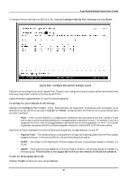
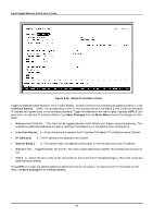
8-port Gigabit Ethernet Switch User's Guide • Ingress Filter - This enables the port to compare the VID tag of an incoming packet with the PVID number assigned to the port. If the two are different, the port filters (drops) the packet. • GVRP - Group VLAN Registration Protocol enables the port to dynamically become a member of a VLAN. • GMRP - Group Multicast Registration Protocol enables the port to dynamically become a member of a multicast group. This function is not supported in the current version of the Switch software. Setting Up IP Interfaces Note: A VLAN that does not have a corresponding IP interface defined for it, will function as a Layer 2 Only VLAN - regardless of the Switch Operation mode. Each VLAN must be configured prior to setting up the corresponding IP interface. An example is presented below: VLAN Name VID Switch Ports System (default) 1 7, 8 Engineering 2 1, 2 Marketing 3 5, 6 Shipping 4 3,4 Table 6-2. VLAN Example - Assigned Ports In this case, 4 IP interfaces are required, so a CIDR notation of 10.32.0.0/10 (or a 10-bit) addressing scheme will work. This addressing scheme will give a subnet mask of 11111111.11000000.00000000.00000000 (binary) or 255.192.0.0 (decimal). Using a 10.xxx.xxx.xxx IP address notation, the above example would give 4 network addresses and 4 subnets. Any IP address from the allowed range of IP addresses for each subnet can be chosen as an IP address for an IP interface on the switch. For this example, we have chosen the next IP address above the network address: VLAN Name VID Network Address IP Address System (default) 1 10.0.0.0 10.0.0.1 Engineering 2 10.64.0.0 10.64.0.1 Marketing 3 10.128.0.0 10.128.0.1 Shipping 4 10.192.0.0 10.192.0.1 Table 6-3. VLAN Example - Assigned IP Addresses The 4 IP interfaces, each with an IP address (listed in the table above), and a subnet mask of 255.192.0.0 can be entered into the Setup IP Interface menu. Note: IP interfaces consist of two parts - a subnet mask and an IP address. 85
-
 1
1 -
2
-
3
-
4
-
5
-
6
-
7
-
8
-
9
-
10
-
11
-
12
-
13
-
14
-
15
-
16
-
17
-
18
-
19
-
20
-
21
-
22
-
23
-
24
-
25
-
26
-
27
-
28
-
29
-
30
-
31
-
32
-
33
-
34
-
35
-
36
-
37
-
38
-
39
-
40
-
41
-
42
-
43
-
44
-
45
-
46
-
47
-
48
-
49
-
50
-
51
-
52
-
53
-
54
-
55
-
56
-
57
-
58
-
59
-
60
-
61
-
62
-
63
-
64
-
65
-
66
-
67
-
68
-
69
-
70
-
71
-
72
-
73
-
74
-
75
-
76
-
77
-
78
-
79
-
80
-
81
-
82
-
83
-
84
-
85
-
86
-
87
-
88
-
89
-
 90
90 -
 91
91 -
 92
92 -
 93
93 -
 94
94 -
 95
95 -
 96
96 -
 97
97 -
 98
98 -
 99
99 -
 100
100 -
101
-
102
-
103
-
104
-
105
-
106
-
107
-
108
-
109
-
110
-
111
-
112
-
113
-
114
-
115
-
116
-
117
-
118
-
119
-
120
-
121
-
122
-
123
-
124
-
125
-
126
-
127
-
128
-
129
-
130
-
131
-
132
-
133
-
134
-
135
-
136
-
137
-
138
-
139
-
140
-
141
-
142
-
143
-
144
-
145
-
146
-
147
-
148
-
149
-
150
-
151
-
152
-
153
-
154
-
155
-
156
-
157
-
158
-
159
-
160
-
161
-
162
-
163
-
164
-
165
-
166
-
167
-
168
-
169
-
170
-
171
-
172
-
173
-
174
-
175
-
176
-
177
-
178
-
179
-
180
-
181
-
182
-
183
-
184
-
185
-
186
-
187
-
188
-
189
-
190
-
191
-
192
-
193
-
194
-
195
-
196
-
197
-
198
-
199
-
200
-
201
-
202
-
203
-
204
-
205
-
206
-
207
-
208
-
209
-
210
-
211
-
212
-
213
-
214
-
215
-
216
-
217
-
218
-
219
-
220
-
221
-
222
-
223
-
224
-
225
-
226
-
227
-
228
-
229
-
230
-
231
-
232
-
233
-
234
-
235
-
236
-
237
 |
 |