D-Link DGS-3308FG Product Manual - Page 150
Etwork, Anagement
 |
UPC - 790069239373
View all D-Link DGS-3308FG manuals
Add to My Manuals
Save this manual to your list of manuals |
Page 150 highlights
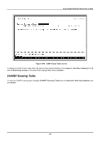
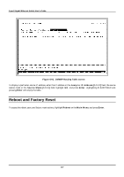
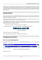
8-port Gigabit Ethernet Switch User's Guide 7 WEB-BASED NETWORK MANAGEMENT Introduction The DGS-3308 offers an embedded Web-based (HTML) interface allowing users to manage the Switch from anywhere on the network through a standard browser such as Netscape Navigator/Communicator or Microsoft Internet Explorer. The Web browser acts as a universal access tool and can communicate directly with the Switch using the HTTP protocol. The Web-based management module and the Console program (and Telnet) are different ways to access the same internal switching software and configure it. Thus, all settings encountered in Web-based management are the same as those found in the console program. Note: This Web-based Management Module does not accept Chinese language input (or other languages requiring 2 bytes per character). Where there is a difference in the setup of the Switch between its two operational modes (Layer 2 Only and IP Routing), the sections are divided to correspond with the switch operating mode that is applicable. Note: IP Routing mode switch configuration settings that are saved NV-RAM using Save Changes from the Main Menu are retained in the switch's memory when the operational mode is changed. IP Routing mode settings are simply inactive when the switch is in Layer 2 Only mode. Before You Start The DGS-3308 Gigabit Ethernet Layer 3 Switch supports a wide array of functions and gives great flexibility and increased network performance by eliminating the routing bottleneck between the WAN or Internet and the Intranet. Its function in a network can be thought of as a new generation of router that performs routing functions in hardware, rather than software. It is a router that also has up to eight independent Gigabit Ethernet collision domains - each of which can be assigned an IP subnet. This flexibility and rich feature set requires a bit of thought to arrive at a deployment strategy that will maximize the potential of the Switch. General Deployment Strategy 1. Determine how the network would be best segmented. This is probably done using VLANs in an existing layer 2 switched network. 2. Develop an IP addressing scheme. This involves allocating a block of IP addresses to each network segment. Each network subnet is then assigned a network address and a subnet mask. See Chapter 5, "Switch Management and Operating Concepts," in the section titled IP Addressing and Subnetting for more information. 140
-
 1
1 -
2
-
3
-
4
-
5
-
6
-
7
-
8
-
9
-
10
-
11
-
12
-
13
-
14
-
15
-
16
-
17
-
18
-
19
-
20
-
21
-
22
-
23
-
24
-
25
-
26
-
27
-
28
-
29
-
30
-
31
-
32
-
33
-
34
-
35
-
36
-
37
-
38
-
39
-
40
-
41
-
42
-
43
-
44
-
45
-
46
-
47
-
48
-
49
-
50
-
51
-
52
-
53
-
54
-
55
-
56
-
57
-
58
-
59
-
60
-
61
-
62
-
63
-
64
-
65
-
66
-
67
-
68
-
69
-
70
-
71
-
72
-
73
-
74
-
75
-
76
-
77
-
78
-
79
-
80
-
81
-
82
-
83
-
84
-
85
-
86
-
87
-
88
-
89
-
90
-
91
-
92
-
93
-
94
-
95
-
96
-
97
-
98
-
99
-
100
-
101
-
102
-
103
-
104
-
105
-
106
-
107
-
108
-
109
-
110
-
111
-
112
-
113
-
114
-
115
-
116
-
117
-
118
-
119
-
120
-
121
-
122
-
123
-
124
-
125
-
126
-
127
-
128
-
129
-
130
-
131
-
132
-
133
-
134
-
135
-
136
-
137
-
138
-
139
-
140
-
141
-
142
-
143
-
144
-
 145
145 -
 146
146 -
 147
147 -
 148
148 -
 149
149 -
 150
150 -
 151
151 -
 152
152 -
 153
153 -
 154
154 -
 155
155 -
156
-
157
-
158
-
159
-
160
-
161
-
162
-
163
-
164
-
165
-
166
-
167
-
168
-
169
-
170
-
171
-
172
-
173
-
174
-
175
-
176
-
177
-
178
-
179
-
180
-
181
-
182
-
183
-
184
-
185
-
186
-
187
-
188
-
189
-
190
-
191
-
192
-
193
-
194
-
195
-
196
-
197
-
198
-
199
-
200
-
201
-
202
-
203
-
204
-
205
-
206
-
207
-
208
-
209
-
210
-
211
-
212
-
213
-
214
-
215
-
216
-
217
-
218
-
219
-
220
-
221
-
222
-
223
-
224
-
225
-
226
-
227
-
228
-
229
-
230
-
231
-
232
-
233
-
234
-
235
-
236
-
237
 |
 |