D-Link DGS-3308FG Product Manual - Page 38
Spanning Tree Protocol
 |
UPC - 790069239373
View all D-Link DGS-3308FG manuals
Add to My Manuals
Save this manual to your list of manuals |
Page 38 highlights
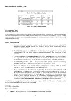
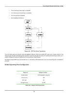
8-port Gigabit Ethernet Switch User's Guide An example is presented below: VLAN Name VID Switch Ports System (default) 1 7, 8 Engineering 2 1, 2 Marketing 3 5, 6 Shipping 4 3,4 Table 5-5. VLAN Example - Assigned Ports In this case, 4 IP interfaces are required, so a CIDR notation of 10.32.0.0/10 (or a 10-bit) addressing scheme will work. This addressing scheme will give a subnet mask of 11111111.11000000.00000000.00000000 (binary) or 255.192.0.0 (decimal). Using a 10.xxx.xxx.xxx IP address notation, the above example would give 4 network addresses and 4 subnets. Any IP address from the allowed range of IP addresses for each subnet can be chosen as an IP address for an IP interface on the switch. For this example, we have chosen the next IP address above the network address: VLAN Name VID Network Address IP Address System (default) 1 10.0.0.0 10.0.0.1 Engineering 2 10.64.0.0 10.64.0.1 Marketing 3 10.128.0.0 10.128.0.1 Shipping 4 10.192.0.0 10.192.0.1 Table 5-6. VLAN Example - Assigned IP Addresses The 4 IP interfaces, each with an IP address (listed in the table above), and a subnet mask of 255.192.0.0 can be entered into the Setup IP Interface menu. Spanning Tree Protocol The IEEE 802.1D Spanning Tree Protocol allows for the blocking of links between switches that form loops within the network. When multiple links between switches are detected, a primary link is established. Duplicated links are blocked from use and become standby links. The protocol allows for the duplicate links to be used in the event of a failure of the primary link. Once the Spanning Tree Protocol is configured and enabled, primary links are established and duplicated links are blocked automatically. The reactivation of the blocked links (at the time of a primary link failure) is also accomplished automatically - without operator intervention. This automatic network reconfiguration provides maximum uptime to network users. However, the concepts of the Spanning Tree Algorithm and protocol are a complicated and complex subject and must be fully researched and understood. It is possible to cause serious degradation of the performance of the network if the Spanning Tree is incorrectly configured. Please read the following before making any changes from the default values. The DGS-3308 STP allows two levels of spanning trees to be configured. The first level constructs a spanning tree on the links between switches. This is referred to as the Switch or Global level. The second level is on a port group basis. Groups of ports are configured as being members of a spanning tree and the algorithm and protocol are applied to the group of ports. This is referred to as the Port or VLAN level. 28
-
 1
1 -
2
-
3
-
4
-
5
-
6
-
7
-
8
-
9
-
10
-
11
-
12
-
13
-
14
-
15
-
16
-
17
-
18
-
19
-
20
-
21
-
22
-
23
-
24
-
25
-
26
-
27
-
28
-
29
-
30
-
31
-
32
-
 33
33 -
 34
34 -
 35
35 -
 36
36 -
 37
37 -
 38
38 -
 39
39 -
 40
40 -
 41
41 -
 42
42 -
 43
43 -
44
-
45
-
46
-
47
-
48
-
49
-
50
-
51
-
52
-
53
-
54
-
55
-
56
-
57
-
58
-
59
-
60
-
61
-
62
-
63
-
64
-
65
-
66
-
67
-
68
-
69
-
70
-
71
-
72
-
73
-
74
-
75
-
76
-
77
-
78
-
79
-
80
-
81
-
82
-
83
-
84
-
85
-
86
-
87
-
88
-
89
-
90
-
91
-
92
-
93
-
94
-
95
-
96
-
97
-
98
-
99
-
100
-
101
-
102
-
103
-
104
-
105
-
106
-
107
-
108
-
109
-
110
-
111
-
112
-
113
-
114
-
115
-
116
-
117
-
118
-
119
-
120
-
121
-
122
-
123
-
124
-
125
-
126
-
127
-
128
-
129
-
130
-
131
-
132
-
133
-
134
-
135
-
136
-
137
-
138
-
139
-
140
-
141
-
142
-
143
-
144
-
145
-
146
-
147
-
148
-
149
-
150
-
151
-
152
-
153
-
154
-
155
-
156
-
157
-
158
-
159
-
160
-
161
-
162
-
163
-
164
-
165
-
166
-
167
-
168
-
169
-
170
-
171
-
172
-
173
-
174
-
175
-
176
-
177
-
178
-
179
-
180
-
181
-
182
-
183
-
184
-
185
-
186
-
187
-
188
-
189
-
190
-
191
-
192
-
193
-
194
-
195
-
196
-
197
-
198
-
199
-
200
-
201
-
202
-
203
-
204
-
205
-
206
-
207
-
208
-
209
-
210
-
211
-
212
-
213
-
214
-
215
-
216
-
217
-
218
-
219
-
220
-
221
-
222
-
223
-
224
-
225
-
226
-
227
-
228
-
229
-
230
-
231
-
232
-
233
-
234
-
235
-
236
-
237
 |
 |