D-Link DGS-3308FG Product Manual - Page 187
Port Trunking Configuration, Group, Master Port, Group Width, Method, Anchor
 |
UPC - 790069239373
View all D-Link DGS-3308FG manuals
Add to My Manuals
Save this manual to your list of manuals |
Page 187 highlights
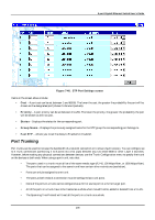
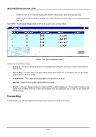
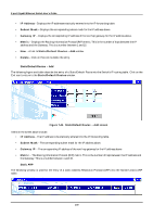
8-port Gigabit Ethernet Switch User's Guide • Enable the trunk prior to connecting any cable between the switches to avoid creating a data loop. • Disconnect all trunk port cables or disable the trunk ports before removing a port trunk to avoid creating a data loop. Use the Port Trunking Configuration screen to set up port trunks as shown below. Figure 7-41. Port Trunking screen Items on the screen above include: • Group ID - The Switch allows up to 4 port trunks groups to be configured. The group number identifies each of these groups. • Master Port - The port of the trunk group whose configuration (speed, full- or half-duplex, etc.) will be used by all of the ports in the trunk group. • Group Width - The number of contiguous ports in the selected trunk group. • Method - Allows the trunk group to be Enabled or Disabled. • Anchor - This port displays what port is receiving BPDUs, SNMP packets, etc. This is usually the same as the Master Port. However, if the link is down for the Master Port, the closest port with a valid link will become the new anchor port. Forwarding The following figures and tables describe how to setup static packet forwarding on the Switch. 177
-
 1
1 -
2
-
3
-
4
-
5
-
6
-
7
-
8
-
9
-
10
-
11
-
12
-
13
-
14
-
15
-
16
-
17
-
18
-
19
-
20
-
21
-
22
-
23
-
24
-
25
-
26
-
27
-
28
-
29
-
30
-
31
-
32
-
33
-
34
-
35
-
36
-
37
-
38
-
39
-
40
-
41
-
42
-
43
-
44
-
45
-
46
-
47
-
48
-
49
-
50
-
51
-
52
-
53
-
54
-
55
-
56
-
57
-
58
-
59
-
60
-
61
-
62
-
63
-
64
-
65
-
66
-
67
-
68
-
69
-
70
-
71
-
72
-
73
-
74
-
75
-
76
-
77
-
78
-
79
-
80
-
81
-
82
-
83
-
84
-
85
-
86
-
87
-
88
-
89
-
90
-
91
-
92
-
93
-
94
-
95
-
96
-
97
-
98
-
99
-
100
-
101
-
102
-
103
-
104
-
105
-
106
-
107
-
108
-
109
-
110
-
111
-
112
-
113
-
114
-
115
-
116
-
117
-
118
-
119
-
120
-
121
-
122
-
123
-
124
-
125
-
126
-
127
-
128
-
129
-
130
-
131
-
132
-
133
-
134
-
135
-
136
-
137
-
138
-
139
-
140
-
141
-
142
-
143
-
144
-
145
-
146
-
147
-
148
-
149
-
150
-
151
-
152
-
153
-
154
-
155
-
156
-
157
-
158
-
159
-
160
-
161
-
162
-
163
-
164
-
165
-
166
-
167
-
168
-
169
-
170
-
171
-
172
-
173
-
174
-
175
-
176
-
177
-
178
-
179
-
180
-
181
-
 182
182 -
 183
183 -
 184
184 -
 185
185 -
 186
186 -
 187
187 -
 188
188 -
 189
189 -
 190
190 -
 191
191 -
 192
192 -
193
-
194
-
195
-
196
-
197
-
198
-
199
-
200
-
201
-
202
-
203
-
204
-
205
-
206
-
207
-
208
-
209
-
210
-
211
-
212
-
213
-
214
-
215
-
216
-
217
-
218
-
219
-
220
-
221
-
222
-
223
-
224
-
225
-
226
-
227
-
228
-
229
-
230
-
231
-
232
-
233
-
234
-
235
-
236
-
237
 |
 |
