D-Link DGS-3308FG Product Manual - Page 167
Con Layer 3 - IP Networking
 |
UPC - 790069239373
View all D-Link DGS-3308FG manuals
Add to My Manuals
Save this manual to your list of manuals |
Page 167 highlights
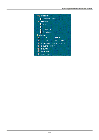
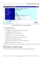
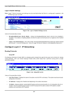
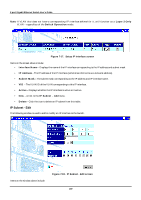
8-port Gigabit Ethernet Switch User's Guide Layer 2 Switch Settings Note: Layer 2 Switch functions and settings are also available when the Switch is configured to operate in the IP Routing (Layer 3) mode. Figure 7-14. Layer 2 Switch Settings screen Items on the screen above include: • Broadcast/Multicast Storm Mode - Allows the Broadcast/Multicast Storm control to be Enabled or Disabled. This enables or disables, globally, the Switch's reaction to Multicast storms, triggered at the threshold set below. • Upper Threshold (Kpps) - This is the number of thousands Broadcast/Multicast packets per second received by the Switch - on one of the base ports - that will trigger the Switch's reaction to a Broadcast/Multicast storm. Configure Layer 3 - IP Networking Routing Protocols Setup RIP The Routing Information Protocol (RIP) is a distance-vector protocol that uses the hop count as its criteria for making routing decisions. RIP is an Interior Gateway Protocol (IGP), which means that it performs routing within a single autonomous system. Figure 7-15. Setup RIP screen Items on the screen above include: • Interface Name - Displays the name of the subnet on which RIP is to be setup. This subnet must be previously configured on the Switch. • IP Address - Displays the IP address corresponding to the subnet name above. • Tx Mode - Displays whether transmitted RIP packets will be structured as Rip V1, V1 Compatible, Rip V2, or Disable. This entry specifies which version of the RIP protocol will be used to transmit RIP packets. Disable prevents the transmission of RIP packets. 157
-
 1
1 -
2
-
3
-
4
-
5
-
6
-
7
-
8
-
9
-
10
-
11
-
12
-
13
-
14
-
15
-
16
-
17
-
18
-
19
-
20
-
21
-
22
-
23
-
24
-
25
-
26
-
27
-
28
-
29
-
30
-
31
-
32
-
33
-
34
-
35
-
36
-
37
-
38
-
39
-
40
-
41
-
42
-
43
-
44
-
45
-
46
-
47
-
48
-
49
-
50
-
51
-
52
-
53
-
54
-
55
-
56
-
57
-
58
-
59
-
60
-
61
-
62
-
63
-
64
-
65
-
66
-
67
-
68
-
69
-
70
-
71
-
72
-
73
-
74
-
75
-
76
-
77
-
78
-
79
-
80
-
81
-
82
-
83
-
84
-
85
-
86
-
87
-
88
-
89
-
90
-
91
-
92
-
93
-
94
-
95
-
96
-
97
-
98
-
99
-
100
-
101
-
102
-
103
-
104
-
105
-
106
-
107
-
108
-
109
-
110
-
111
-
112
-
113
-
114
-
115
-
116
-
117
-
118
-
119
-
120
-
121
-
122
-
123
-
124
-
125
-
126
-
127
-
128
-
129
-
130
-
131
-
132
-
133
-
134
-
135
-
136
-
137
-
138
-
139
-
140
-
141
-
142
-
143
-
144
-
145
-
146
-
147
-
148
-
149
-
150
-
151
-
152
-
153
-
154
-
155
-
156
-
157
-
158
-
159
-
160
-
161
-
 162
162 -
 163
163 -
 164
164 -
 165
165 -
 166
166 -
 167
167 -
 168
168 -
 169
169 -
 170
170 -
 171
171 -
 172
172 -
173
-
174
-
175
-
176
-
177
-
178
-
179
-
180
-
181
-
182
-
183
-
184
-
185
-
186
-
187
-
188
-
189
-
190
-
191
-
192
-
193
-
194
-
195
-
196
-
197
-
198
-
199
-
200
-
201
-
202
-
203
-
204
-
205
-
206
-
207
-
208
-
209
-
210
-
211
-
212
-
213
-
214
-
215
-
216
-
217
-
218
-
219
-
220
-
221
-
222
-
223
-
224
-
225
-
226
-
227
-
228
-
229
-
230
-
231
-
232
-
233
-
234
-
235
-
236
-
237
 |
 |
