D-Link DGS-3308FG Product Manual - Page 33
Q Vlans
 |
UPC - 790069239373
View all D-Link DGS-3308FG manuals
Add to My Manuals
Save this manual to your list of manuals |
Page 33 highlights
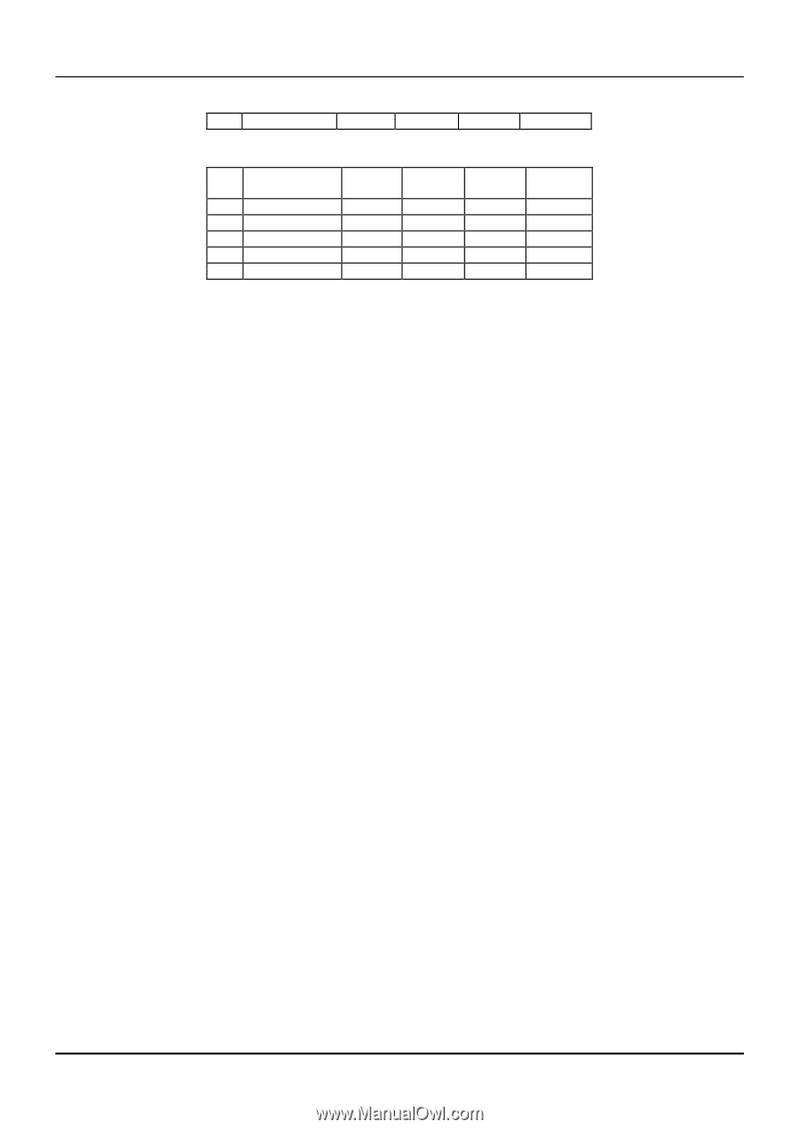
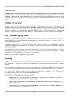
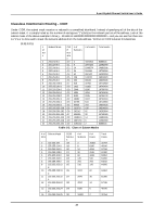
8-port Gigabit Ethernet Switch User's Guide 2 Table 5-3. Class B Subnet Masks # of Subnet Mask CIDR # of Bits Notation Subnets 2 255.255.255.192 /26 2 3 255.255.255.224 /27 6 4 255.255.255.240 /28 14 5 255.255.255.248 /29 30 6 255.255.255.252 /30 62 # of Hosts 62 30 14 6 2 Table 5-4. Class C Subnet Masks Total Hosts 124 180 196 180 124 802.1Q VLANs A VLAN is a collection of end nodes grouped by logic instead of physical location. End nodes that frequently communicate with each other are assigned to the same VLAN, regardless of where they are physically on the network. Logically, a VLAN can be equated to a broadcast domain, because broadcast packets are forwarded to only members of the VLAN on which the broadcast was initiated. Notes About VLANs 1. N o matter what basis is used to uniquely identify end nodes and assign these nodes VLAN membership, packets cannot cross VLANs without a network device performing a routing function between the VLANs. 2. The DGS-3308 supports only IEEE 802.1Q VLANs. The port untagging function can be used to remove the 802.1 tag from packet headers to maintain compatibility with devices that are tagunaware. 3. The Switch's default - in both Layer 2 Only mode and IP Routing mode - is to assign all ports to a single 802.1Q VLAN named DEFAULT_VLAN. As new VLANs are created, the member ports assigned to the new VLAN will be removed from the DEFAULT_ VLAN port member list. 4. The DEFAULT_VLAN has a VID = 1. An IP interface called System in the IP interface entry menu also has a VID = 1, and therefore corresponds to the DEFAULT_VLAN. 5. There is no difference in the creation, deletion, configuration, or editing of 802.1Q VLANs whether the Switch is in Layer 2 Only, or IP Routing mode. 6. There is a difference in the behavior of VLANs when the Switch is in Layer 2 Only or IP Routing mode. In Layer 2 Only mode, network resources cannot be shared across VLANs. In IP Routing mode, network resources are shared via routing. The Switch allows the assignment of an IP interface to each VLAN, in IP Routing mode. The VLANs must be configured before setting up the IP interfaces. In addition, an IP addressing scheme must be determined. Some consideration is required to arrive at a suitable combination of VLANs and IP interfaces. See the section titled IP Addressing and Subnetting in Chapter 5 for more information. A VLAN that is not assigned an IP interface will behave as a layer 2 VLAN - and IP routing will not be possible on this VLAN regardless of the Switch's operating mode. IEEE 802.1Q VLANs Some relevant terms: • Tagging - The act of putting 802.1Q VLAN information into the header of a packet. 23
-
 1
1 -
2
-
3
-
4
-
5
-
6
-
7
-
8
-
9
-
10
-
11
-
12
-
13
-
14
-
15
-
16
-
17
-
18
-
19
-
20
-
21
-
22
-
23
-
24
-
25
-
26
-
27
-
 28
28 -
 29
29 -
 30
30 -
 31
31 -
 32
32 -
 33
33 -
 34
34 -
 35
35 -
 36
36 -
 37
37 -
 38
38 -
39
-
40
-
41
-
42
-
43
-
44
-
45
-
46
-
47
-
48
-
49
-
50
-
51
-
52
-
53
-
54
-
55
-
56
-
57
-
58
-
59
-
60
-
61
-
62
-
63
-
64
-
65
-
66
-
67
-
68
-
69
-
70
-
71
-
72
-
73
-
74
-
75
-
76
-
77
-
78
-
79
-
80
-
81
-
82
-
83
-
84
-
85
-
86
-
87
-
88
-
89
-
90
-
91
-
92
-
93
-
94
-
95
-
96
-
97
-
98
-
99
-
100
-
101
-
102
-
103
-
104
-
105
-
106
-
107
-
108
-
109
-
110
-
111
-
112
-
113
-
114
-
115
-
116
-
117
-
118
-
119
-
120
-
121
-
122
-
123
-
124
-
125
-
126
-
127
-
128
-
129
-
130
-
131
-
132
-
133
-
134
-
135
-
136
-
137
-
138
-
139
-
140
-
141
-
142
-
143
-
144
-
145
-
146
-
147
-
148
-
149
-
150
-
151
-
152
-
153
-
154
-
155
-
156
-
157
-
158
-
159
-
160
-
161
-
162
-
163
-
164
-
165
-
166
-
167
-
168
-
169
-
170
-
171
-
172
-
173
-
174
-
175
-
176
-
177
-
178
-
179
-
180
-
181
-
182
-
183
-
184
-
185
-
186
-
187
-
188
-
189
-
190
-
191
-
192
-
193
-
194
-
195
-
196
-
197
-
198
-
199
-
200
-
201
-
202
-
203
-
204
-
205
-
206
-
207
-
208
-
209
-
210
-
211
-
212
-
213
-
214
-
215
-
216
-
217
-
218
-
219
-
220
-
221
-
222
-
223
-
224
-
225
-
226
-
227
-
228
-
229
-
230
-
231
-
232
-
233
-
234
-
235
-
236
-
237
 |
 |