D-Link DGS-3308FG Product Manual - Page 193
BOOTP/DHCP Relay Interface Setup
 |
UPC - 790069239373
View all D-Link DGS-3308FG manuals
Add to My Manuals
Save this manual to your list of manuals |
Page 193 highlights
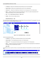
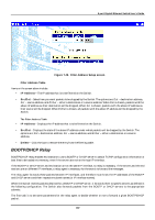
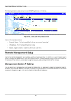
8-port Gigabit Ethernet Switch User's Guide Figure 7-49. BOOTP/DHCP Relay screen Items on the screen above include: • BOOTP/DHCP Relay Status - Allows the BootP/DHCP relay function to be Enabled or Disabled. • BOOTP HOPS Count Limit - Allows the maximum number of hops (routers) that the BootP messages can be relayed through to be set. If a packet's hop count is more than the hop count limit, the packet is dropped. The range is between 1 and 16 hops. The default value is 4. • BOOTP/DHCP Relay Time Threshold - Sets the minimum time (in seconds) that the switch will wait before forwarding a BOOTREQUEST packet. If the value in the seconds field of the packet is less than the relay time threshold, the packet will be dropped. The range is between 0 and 9999 seconds. The default value is 0 seconds. BOOTP/DHCP Relay Interface Setup The second task is to tell the BOOTP/DHCP relay agent where the servers are located in terms of IP addresses and subnet names (IP interface names). The following figure and table describe how to set up the static Bootp Relay function on the Switch. Figure 7-50. BOOTP/DHCP Relay Interface Setup screen Items on the screen above include: 183
-
 1
1 -
2
-
3
-
4
-
5
-
6
-
7
-
8
-
9
-
10
-
11
-
12
-
13
-
14
-
15
-
16
-
17
-
18
-
19
-
20
-
21
-
22
-
23
-
24
-
25
-
26
-
27
-
28
-
29
-
30
-
31
-
32
-
33
-
34
-
35
-
36
-
37
-
38
-
39
-
40
-
41
-
42
-
43
-
44
-
45
-
46
-
47
-
48
-
49
-
50
-
51
-
52
-
53
-
54
-
55
-
56
-
57
-
58
-
59
-
60
-
61
-
62
-
63
-
64
-
65
-
66
-
67
-
68
-
69
-
70
-
71
-
72
-
73
-
74
-
75
-
76
-
77
-
78
-
79
-
80
-
81
-
82
-
83
-
84
-
85
-
86
-
87
-
88
-
89
-
90
-
91
-
92
-
93
-
94
-
95
-
96
-
97
-
98
-
99
-
100
-
101
-
102
-
103
-
104
-
105
-
106
-
107
-
108
-
109
-
110
-
111
-
112
-
113
-
114
-
115
-
116
-
117
-
118
-
119
-
120
-
121
-
122
-
123
-
124
-
125
-
126
-
127
-
128
-
129
-
130
-
131
-
132
-
133
-
134
-
135
-
136
-
137
-
138
-
139
-
140
-
141
-
142
-
143
-
144
-
145
-
146
-
147
-
148
-
149
-
150
-
151
-
152
-
153
-
154
-
155
-
156
-
157
-
158
-
159
-
160
-
161
-
162
-
163
-
164
-
165
-
166
-
167
-
168
-
169
-
170
-
171
-
172
-
173
-
174
-
175
-
176
-
177
-
178
-
179
-
180
-
181
-
182
-
183
-
184
-
185
-
186
-
187
-
 188
188 -
 189
189 -
 190
190 -
 191
191 -
 192
192 -
 193
193 -
 194
194 -
 195
195 -
 196
196 -
 197
197 -
 198
198 -
199
-
200
-
201
-
202
-
203
-
204
-
205
-
206
-
207
-
208
-
209
-
210
-
211
-
212
-
213
-
214
-
215
-
216
-
217
-
218
-
219
-
220
-
221
-
222
-
223
-
224
-
225
-
226
-
227
-
228
-
229
-
230
-
231
-
232
-
233
-
234
-
235
-
236
-
237
 |
 |
