D-Link DGS-3308FG Product Manual - Page 88
Advanced Setup
 |
UPC - 790069239373
View all D-Link DGS-3308FG manuals
Add to My Manuals
Save this manual to your list of manuals |
Page 88 highlights
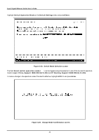
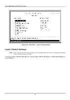
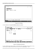
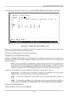
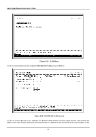
8-port Gigabit Ethernet Switch User's Guide • Interface name:[ ] - The name of the IP interface on which RIP is to be setup. This interface must be previously configured on the Switch. • TX Mode: - Toggle among Disabled, V1 Only, V1 Compatible, and V2 Only. This entry specifies which version of the RIP protocol will be used to transmit RIP packets. Disabled prevents the transmission of RIP packets. • RX Mode: - Toggle among Disabled, V1 Only, V2 Only, and V1 and V2. This entry specifies which version of the RIP protocol will be used to interpret received RIP packets. Disabled prevents the reception of RIP packets. • Authentication: - Toggle between Enabled and Disabled. When authentication is enabled, a password is used to authenticate communication between routers on the network. Authentication is only supported when RIP is in V1 Compatible or V2 only mode. • Password:[ ] - A password to be used to authenticate communication between routers on the network. Advanced Setup The switch operation mode setting changes the menus and configuration options for the Advanced Setup of the Switch. This section of the manual is therefore divided into two sections for each Advanced Setup menu item to reflect the two switch operation modes - Layer 2 with IEEE 802.1Q VLAN support and IP Routing with IEEE 802.1Q VLAN support. Where there is no difference in the setup between the two switch operation modes, only one section will be presented. Configuring VLANs Note: The Switch allows the assignment of an IP interface to each VLAN, in IP Routing mode. The VLANs must be configured before setting up the IP interfaces. VLANs in Layer 2 Only Mode The Switch reserves one VLAN, VID = 1, called the DEFAULT_VLAN for internal use. The factory default setting assigns all ports on the Switch to the DEFAULT_VLAN. As new VLANs are configured, there respective member ports are removed from the DEFAULT_VLAN. If the DEFAULT_VLAN is reconfigured, all ports are again assigned to it. Ports that are not desired to be part of the DEFAULT_VLAN are removed during the configuration. Packets cannot cross layer 2 VLANs. If a member of one layer 2 VLAN wants to connect to another layer 2 VLAN, it must be through a router. VLANs by Switch Operating Mode - Layer 2 Only and IP Routing Note: The Switch's default - in both Layer 2 Only mode and IP Routing mode - is to assign all ports to a single 802.1Q VLAN named DEFAULT_VLAN. As new VLANs are created, the member ports assigned to the new VLAN will be removed from the default VLAN port member list. Note: The DEFAULT_VLAN has a VID = 1. An IP interface called System in the IP interface entry menu also has a VID = 1, and therefore corresponds to the DEFAULT_VLAN. To create a new 802.1Q VLAN: The VLAN menu adds an entry to edit the VLAN definitions and to configure the port settings for IEEE 802.1Q VLAN support. Highlight VLANs from the Main Menu and press Enter. 78
-
 1
1 -
2
-
3
-
4
-
5
-
6
-
7
-
8
-
9
-
10
-
11
-
12
-
13
-
14
-
15
-
16
-
17
-
18
-
19
-
20
-
21
-
22
-
23
-
24
-
25
-
26
-
27
-
28
-
29
-
30
-
31
-
32
-
33
-
34
-
35
-
36
-
37
-
38
-
39
-
40
-
41
-
42
-
43
-
44
-
45
-
46
-
47
-
48
-
49
-
50
-
51
-
52
-
53
-
54
-
55
-
56
-
57
-
58
-
59
-
60
-
61
-
62
-
63
-
64
-
65
-
66
-
67
-
68
-
69
-
70
-
71
-
72
-
73
-
74
-
75
-
76
-
77
-
78
-
79
-
80
-
81
-
82
-
 83
83 -
 84
84 -
 85
85 -
 86
86 -
 87
87 -
 88
88 -
 89
89 -
 90
90 -
 91
91 -
 92
92 -
 93
93 -
94
-
95
-
96
-
97
-
98
-
99
-
100
-
101
-
102
-
103
-
104
-
105
-
106
-
107
-
108
-
109
-
110
-
111
-
112
-
113
-
114
-
115
-
116
-
117
-
118
-
119
-
120
-
121
-
122
-
123
-
124
-
125
-
126
-
127
-
128
-
129
-
130
-
131
-
132
-
133
-
134
-
135
-
136
-
137
-
138
-
139
-
140
-
141
-
142
-
143
-
144
-
145
-
146
-
147
-
148
-
149
-
150
-
151
-
152
-
153
-
154
-
155
-
156
-
157
-
158
-
159
-
160
-
161
-
162
-
163
-
164
-
165
-
166
-
167
-
168
-
169
-
170
-
171
-
172
-
173
-
174
-
175
-
176
-
177
-
178
-
179
-
180
-
181
-
182
-
183
-
184
-
185
-
186
-
187
-
188
-
189
-
190
-
191
-
192
-
193
-
194
-
195
-
196
-
197
-
198
-
199
-
200
-
201
-
202
-
203
-
204
-
205
-
206
-
207
-
208
-
209
-
210
-
211
-
212
-
213
-
214
-
215
-
216
-
217
-
218
-
219
-
220
-
221
-
222
-
223
-
224
-
225
-
226
-
227
-
228
-
229
-
230
-
231
-
232
-
233
-
234
-
235
-
236
-
237
 |
 |