D-Link DGS-3308FG Product Manual - Page 79
Remote Management Setup
 |
UPC - 790069239373
View all D-Link DGS-3308FG manuals
Add to My Manuals
Save this manual to your list of manuals |
Page 79 highlights
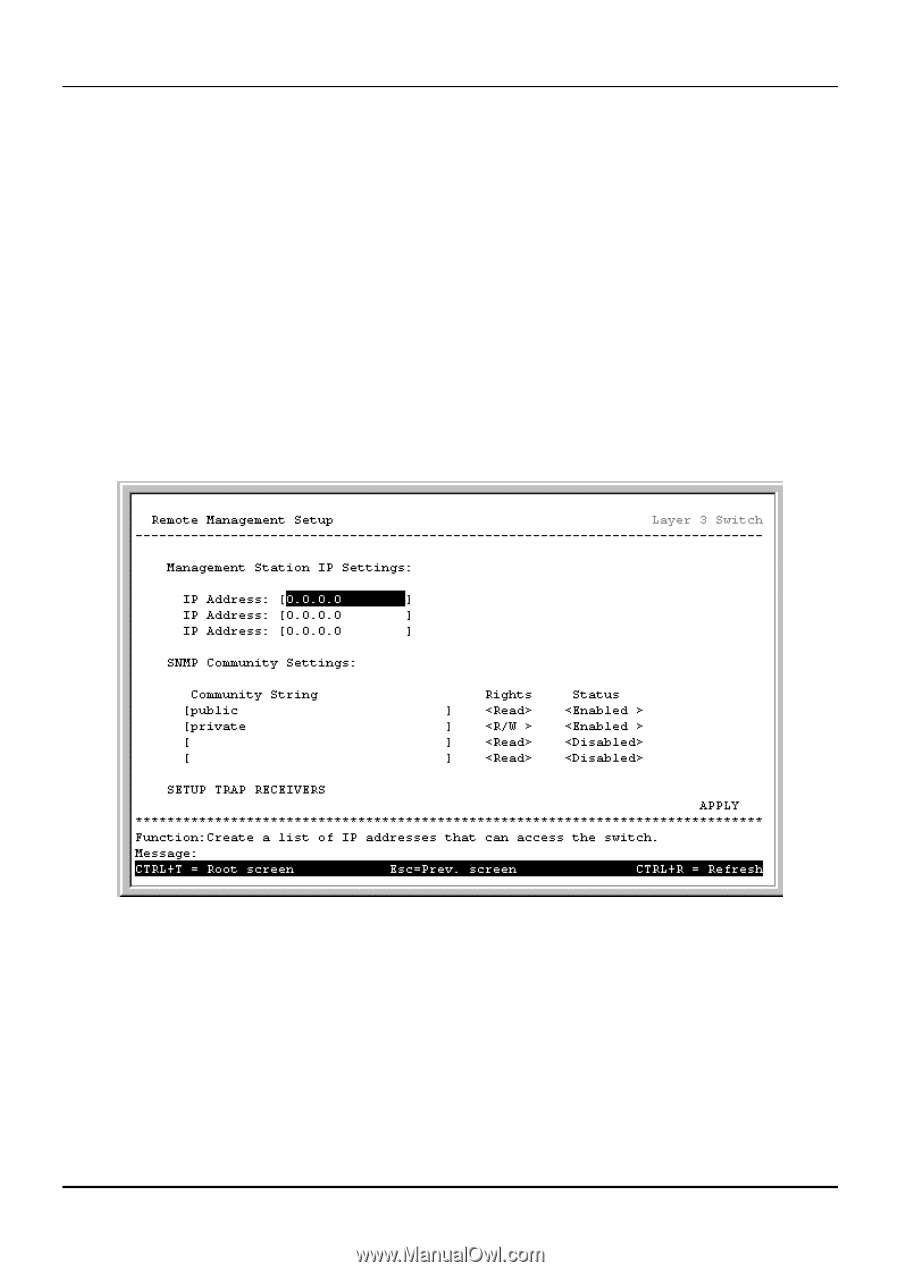
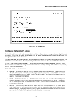
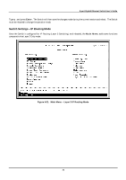
8-port Gigabit Ethernet Switch User's Guide § Subnet Mask - A Bitmask that determines the extent of the subnet that the Switch is on. Should be of the form xxx.xxx.xxx.xxx, where each xxx is a number (represented in decimal) between 0 and 255. The value should be 255.0.0.0 for a Class A network, 255.255.0.0 for a Class B network, and 255.255.255.0 for a Class C network, but custom subnet masks are allowed. § Default Gateway - IP address that determines where packets with a destination address outside the current subnet should be sent. This is usually the address of a router or a host acting as an IP gateway. If your network is not part of an intranet, or you do not want the Switch to be accessible outside your local network, you can leave this field unchanged. • Management VID - Allows the input of a VLAN VID to restrict access to the management module on the Switch to a single VLAN. Remote Management Setup This allows the Switch to send traps (messages about errors, etc.) to management stations on the network. Highlight Remote Management Setup on the Main Menu and press Enter. The trap recipients can be setup from the following screen: Figure 6-14. Remote Management Setup screen The IP Address field is the IP address of a management station (usually a computer) that is configured to receive the SNMP traps from the Switch. The SNMP Community String is similar to a password in that stations that do not know the correct string cannot receive or request SNMP information from the Switch. The Status field can be toggled between Enabled and Disabled to enable or disable the receipt of SNMP traps by the listed management stations. Note: Up to four SNMP trap recipients can be entered. 69
-
 1
1 -
2
-
3
-
4
-
5
-
6
-
7
-
8
-
9
-
10
-
11
-
12
-
13
-
14
-
15
-
16
-
17
-
18
-
19
-
20
-
21
-
22
-
23
-
24
-
25
-
26
-
27
-
28
-
29
-
30
-
31
-
32
-
33
-
34
-
35
-
36
-
37
-
38
-
39
-
40
-
41
-
42
-
43
-
44
-
45
-
46
-
47
-
48
-
49
-
50
-
51
-
52
-
53
-
54
-
55
-
56
-
57
-
58
-
59
-
60
-
61
-
62
-
63
-
64
-
65
-
66
-
67
-
68
-
69
-
70
-
71
-
72
-
73
-
 74
74 -
 75
75 -
 76
76 -
 77
77 -
 78
78 -
 79
79 -
 80
80 -
 81
81 -
 82
82 -
 83
83 -
 84
84 -
85
-
86
-
87
-
88
-
89
-
90
-
91
-
92
-
93
-
94
-
95
-
96
-
97
-
98
-
99
-
100
-
101
-
102
-
103
-
104
-
105
-
106
-
107
-
108
-
109
-
110
-
111
-
112
-
113
-
114
-
115
-
116
-
117
-
118
-
119
-
120
-
121
-
122
-
123
-
124
-
125
-
126
-
127
-
128
-
129
-
130
-
131
-
132
-
133
-
134
-
135
-
136
-
137
-
138
-
139
-
140
-
141
-
142
-
143
-
144
-
145
-
146
-
147
-
148
-
149
-
150
-
151
-
152
-
153
-
154
-
155
-
156
-
157
-
158
-
159
-
160
-
161
-
162
-
163
-
164
-
165
-
166
-
167
-
168
-
169
-
170
-
171
-
172
-
173
-
174
-
175
-
176
-
177
-
178
-
179
-
180
-
181
-
182
-
183
-
184
-
185
-
186
-
187
-
188
-
189
-
190
-
191
-
192
-
193
-
194
-
195
-
196
-
197
-
198
-
199
-
200
-
201
-
202
-
203
-
204
-
205
-
206
-
207
-
208
-
209
-
210
-
211
-
212
-
213
-
214
-
215
-
216
-
217
-
218
-
219
-
220
-
221
-
222
-
223
-
224
-
225
-
226
-
227
-
228
-
229
-
230
-
231
-
232
-
233
-
234
-
235
-
236
-
237
 |
 |