D-Link DGS-3308FG Product Manual - Page 125
Port Trunking, Main Menu, Enter, Group ID, Group Width, Method:<, Apply, Anchor, Master, Save
 |
UPC - 790069239373
View all D-Link DGS-3308FG manuals
Add to My Manuals
Save this manual to your list of manuals |
Page 125 highlights
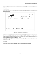
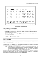
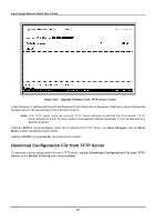
8-port Gigabit Ethernet Switch User's Guide Load balancing is automatically applied to the links in the port trunk group, and a link failure within the group causes the network traffic to be directed to the remaining links in the group. Note: The Spanning Tree Protocol will treat a port trunk group as a single link, on the switch level. On the port level, the STP will use the port parameters of the base port in the calculation of port cost and in determining the state of the link aggregation group. If two redundant port trunk groups are configured on the Switch, STP will block one entire group - in the same way STP will block a single port that has a redundant link. To configure a port trunk group, highlight Port Trunking on the Main Menu and press Enter. Figure 6-65. Port Trunking screen Enter the group ID of one of the six possible port trunk groups configurable on the switch in the Group ID:[1] field. Enter the desired port number in the second field and specify the Group Width:[2]. This is the number of ports, in sequential order from the base port that will be included in the port trunk group. The Method: field can be toggled between TRUNK and Disabled - and is used to turn a port trunk group on or off. This is useful for diagnostics, to quickly isolate a bandwidth intensive network device or to have an absolute backup port trunk group that is not under automatic control. Highlight Apply and press Enter to make the port trunk group configuration active. The Anchor column displays what port is receiving BPDUs, SNMP packets, etc. This is usually the same as the Master port. However, if the link is down for the master port, the closest port with a valid link will become the new anchor port. Use Save Changes from the Main Menu to enter the configuration into NV-RAM. 115
-
 1
1 -
2
-
3
-
4
-
5
-
6
-
7
-
8
-
9
-
10
-
11
-
12
-
13
-
14
-
15
-
16
-
17
-
18
-
19
-
20
-
21
-
22
-
23
-
24
-
25
-
26
-
27
-
28
-
29
-
30
-
31
-
32
-
33
-
34
-
35
-
36
-
37
-
38
-
39
-
40
-
41
-
42
-
43
-
44
-
45
-
46
-
47
-
48
-
49
-
50
-
51
-
52
-
53
-
54
-
55
-
56
-
57
-
58
-
59
-
60
-
61
-
62
-
63
-
64
-
65
-
66
-
67
-
68
-
69
-
70
-
71
-
72
-
73
-
74
-
75
-
76
-
77
-
78
-
79
-
80
-
81
-
82
-
83
-
84
-
85
-
86
-
87
-
88
-
89
-
90
-
91
-
92
-
93
-
94
-
95
-
96
-
97
-
98
-
99
-
100
-
101
-
102
-
103
-
104
-
105
-
106
-
107
-
108
-
109
-
110
-
111
-
112
-
113
-
114
-
115
-
116
-
117
-
118
-
119
-
 120
120 -
 121
121 -
 122
122 -
 123
123 -
 124
124 -
 125
125 -
 126
126 -
 127
127 -
 128
128 -
 129
129 -
 130
130 -
131
-
132
-
133
-
134
-
135
-
136
-
137
-
138
-
139
-
140
-
141
-
142
-
143
-
144
-
145
-
146
-
147
-
148
-
149
-
150
-
151
-
152
-
153
-
154
-
155
-
156
-
157
-
158
-
159
-
160
-
161
-
162
-
163
-
164
-
165
-
166
-
167
-
168
-
169
-
170
-
171
-
172
-
173
-
174
-
175
-
176
-
177
-
178
-
179
-
180
-
181
-
182
-
183
-
184
-
185
-
186
-
187
-
188
-
189
-
190
-
191
-
192
-
193
-
194
-
195
-
196
-
197
-
198
-
199
-
200
-
201
-
202
-
203
-
204
-
205
-
206
-
207
-
208
-
209
-
210
-
211
-
212
-
213
-
214
-
215
-
216
-
217
-
218
-
219
-
220
-
221
-
222
-
223
-
224
-
225
-
226
-
227
-
228
-
229
-
230
-
231
-
232
-
233
-
234
-
235
-
236
-
237
 |
 |
