Dell PowerEdge XL 5133-4 MXL 10/40GbE Switch IO Module FTOS Command Reference - Page 141
Port-Based VLANs, VLANs and Port Tagging, Tagged Frame Format
 |
View all Dell PowerEdge XL 5133-4 manuals
Add to My Manuals
Save this manual to your list of manuals |
Page 141 highlights
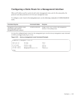
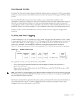
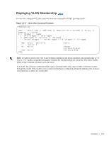
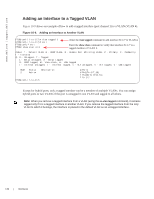
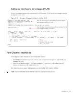
Port-Based VLANs Port-based VLANs are a broadcast domain defined by different ports or interfaces. In FTOS, a port-based VLAN can contain interfaces from different stack units within the chassis. FTOS supports 4094 port-based VLANs. Port-based VLANs offer increased security for traffic, conserve bandwidth, and allow switch segmentation. Interfaces in different VLANs do not communicate with each other, adding some security to the traffic on those interfaces. Different VLANs can communicate between each other by means of IP routing. Because traffic is only broadcast or flooded to the interfaces within a VLAN, the VLAN conserves bandwidth. Finally, you can have multiple VLANs configured on one switch, thus segmenting the device. Interfaces within a port-based VLAN must be in Layer 2 mode and can be tagged or untagged in the VLAN ID. VLANs and Port Tagging To add an interface to a VLAN, it must be in Layer 2 mode. After you place an interface in Layer 2 mode, it is automatically placed in the default VLAN. FTOS supports IEEE 802.1Q tagging at the interface level to filter traffic. When you enable tagging, a tag header is added to the frame after the destination and source MAC addresses. That information is preserved as the frame moves through the network. Figure 10-7 shows the structure of a frame with a tag header. The VLAN ID is inserted in the tag header. Figure 10-7. Tagged Frame Format Ethernet Preamble Destination Address Source Address 6 octets 6 octets Tag Protocol Header Type Data 4 octets 2 octets 45 - 1500 octets Frame Check Sequence 4 octets FN00001B The tag header contains some key information used by FTOS: • The VLAN protocol identifier identifies the frame as tagged according to the IEEE 802.1Q specifications (2 bytes). • Tag control information (TCI) includes the VLAN ID (2 bytes total). The VLAN ID can have 4,096 values, but two are reserved. Note: The insertion of the tag header into the Ethernet frame increases the size of the frame to more than the 1518 bytes specified in the IEEE 802.3 standard. Some devices that are not compliant with IEEE 802.3 may not support the larger frame size. Information contained in the tag header allows the system to prioritize traffic and to forward information to ports associated with a specific VLAN ID. Tagged interfaces can belong to multiple VLANs, while untagged interfaces can belong only to one VLAN. Interfaces | 127
-
 1
1 -
2
-
3
-
4
-
5
-
6
-
7
-
8
-
9
-
10
-
11
-
12
-
13
-
14
-
15
-
16
-
17
-
18
-
19
-
20
-
21
-
22
-
23
-
24
-
25
-
26
-
27
-
28
-
29
-
30
-
31
-
32
-
33
-
34
-
35
-
36
-
37
-
38
-
39
-
40
-
41
-
42
-
43
-
44
-
45
-
46
-
47
-
48
-
49
-
50
-
51
-
52
-
53
-
54
-
55
-
56
-
57
-
58
-
59
-
60
-
61
-
62
-
63
-
64
-
65
-
66
-
67
-
68
-
69
-
70
-
71
-
72
-
73
-
74
-
75
-
76
-
77
-
78
-
79
-
80
-
81
-
82
-
83
-
84
-
85
-
86
-
87
-
88
-
89
-
90
-
91
-
92
-
93
-
94
-
95
-
96
-
97
-
98
-
99
-
100
-
101
-
102
-
103
-
104
-
105
-
106
-
107
-
108
-
109
-
110
-
111
-
112
-
113
-
114
-
115
-
116
-
117
-
118
-
119
-
120
-
121
-
122
-
123
-
124
-
125
-
126
-
127
-
128
-
129
-
130
-
131
-
132
-
133
-
134
-
135
-
 136
136 -
 137
137 -
 138
138 -
 139
139 -
 140
140 -
 141
141 -
 142
142 -
 143
143 -
 144
144 -
 145
145 -
 146
146 -
147
-
148
-
149
-
150
-
151
-
152
-
153
-
154
-
155
-
156
-
157
-
158
-
159
-
160
-
161
-
162
-
163
-
164
-
165
-
166
-
167
-
168
-
169
-
170
-
171
-
172
-
173
-
174
-
175
-
176
-
177
-
178
-
179
-
180
-
181
-
182
-
183
-
184
-
185
-
186
-
187
-
188
-
189
-
190
-
191
-
192
-
193
-
194
-
195
-
196
-
197
-
198
-
199
-
200
-
201
-
202
-
203
-
204
-
205
-
206
-
207
-
208
-
209
-
210
-
211
-
212
-
213
-
214
-
215
-
216
-
217
-
218
-
219
-
220
-
221
-
222
-
223
-
224
-
225
-
226
-
227
-
228
-
229
-
230
-
231
-
232
-
233
-
234
-
235
-
236
-
237
-
238
-
239
-
240
-
241
-
242
-
243
-
244
-
245
-
246
-
247
-
248
-
249
-
250
-
251
-
252
-
253
-
254
-
255
-
256
-
257
-
258
-
259
-
260
-
261
-
262
-
263
-
264
-
265
-
266
-
267
-
268
-
269
-
270
-
271
-
272
-
273
-
274
-
275
-
276
-
277
-
278
-
279
-
280
-
281
-
282
-
283
-
284
-
285
-
286
-
287
-
288
-
289
-
290
 |
 |
