Dell PowerEdge XL 5133-4 MXL 10/40GbE Switch IO Module FTOS Command Reference - Page 221
Stacking Port Numbers, Configuring a Switch Stack
 |
View all Dell PowerEdge XL 5133-4 manuals
Add to My Manuals
Save this manual to your list of manuals |
Page 221 highlights
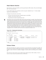
Stacking Port Numbers By default, each Aggregator in Standalone mode is numbered stack-unit 0. Stack-unit numbers are assigned to member switches when the stack comes up. Figure 17-17 shows the numbers of the 40GbE stacking ports on an Aggregator. Figure 17-17. Stack Groups on an Aggregator Stack Unit 0 / Port 37 Stack Unit 0 / Port 33 Configuring a Switch Stack To configure and bring up a switch stack, follow these steps: 1. Connect the 40GbE ports on the base module of two Aggregators using 40G direct attach or QSFP fibre cables. 2. Configure each Aggregator to operate in stacking mode. 3. Reload each Aggregator, one after the other in quick succession. Stacking | 207
-
 1
1 -
2
-
3
-
4
-
5
-
6
-
7
-
8
-
9
-
10
-
11
-
12
-
13
-
14
-
15
-
16
-
17
-
18
-
19
-
20
-
21
-
22
-
23
-
24
-
25
-
26
-
27
-
28
-
29
-
30
-
31
-
32
-
33
-
34
-
35
-
36
-
37
-
38
-
39
-
40
-
41
-
42
-
43
-
44
-
45
-
46
-
47
-
48
-
49
-
50
-
51
-
52
-
53
-
54
-
55
-
56
-
57
-
58
-
59
-
60
-
61
-
62
-
63
-
64
-
65
-
66
-
67
-
68
-
69
-
70
-
71
-
72
-
73
-
74
-
75
-
76
-
77
-
78
-
79
-
80
-
81
-
82
-
83
-
84
-
85
-
86
-
87
-
88
-
89
-
90
-
91
-
92
-
93
-
94
-
95
-
96
-
97
-
98
-
99
-
100
-
101
-
102
-
103
-
104
-
105
-
106
-
107
-
108
-
109
-
110
-
111
-
112
-
113
-
114
-
115
-
116
-
117
-
118
-
119
-
120
-
121
-
122
-
123
-
124
-
125
-
126
-
127
-
128
-
129
-
130
-
131
-
132
-
133
-
134
-
135
-
136
-
137
-
138
-
139
-
140
-
141
-
142
-
143
-
144
-
145
-
146
-
147
-
148
-
149
-
150
-
151
-
152
-
153
-
154
-
155
-
156
-
157
-
158
-
159
-
160
-
161
-
162
-
163
-
164
-
165
-
166
-
167
-
168
-
169
-
170
-
171
-
172
-
173
-
174
-
175
-
176
-
177
-
178
-
179
-
180
-
181
-
182
-
183
-
184
-
185
-
186
-
187
-
188
-
189
-
190
-
191
-
192
-
193
-
194
-
195
-
196
-
197
-
198
-
199
-
200
-
201
-
202
-
203
-
204
-
205
-
206
-
207
-
208
-
209
-
210
-
211
-
212
-
213
-
214
-
215
-
 216
216 -
 217
217 -
 218
218 -
 219
219 -
 220
220 -
 221
221 -
 222
222 -
 223
223 -
 224
224 -
 225
225 -
 226
226 -
227
-
228
-
229
-
230
-
231
-
232
-
233
-
234
-
235
-
236
-
237
-
238
-
239
-
240
-
241
-
242
-
243
-
244
-
245
-
246
-
247
-
248
-
249
-
250
-
251
-
252
-
253
-
254
-
255
-
256
-
257
-
258
-
259
-
260
-
261
-
262
-
263
-
264
-
265
-
266
-
267
-
268
-
269
-
270
-
271
-
272
-
273
-
274
-
275
-
276
-
277
-
278
-
279
-
280
-
281
-
282
-
283
-
284
-
285
-
286
-
287
-
288
-
289
-
290
 |
 |

Stacking
|
207
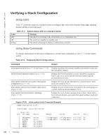
Stacking Port Numbers
By default, each Aggregator in Standalone mode is numbered stack-unit 0. Stack-unit numbers are
assigned to member switches when the stack comes up.
Figure 17-17
shows the numbers of the 40GbE
stacking ports on an Aggregator.
Figure 17-17.
Stack Groups on an Aggregator
Configuring a Switch Stack
To configure and bring up a switch stack, follow these steps:
1.
Connect the 40GbE ports on the base module of two Aggregators using 40G direct attach or QSFP
fibre cables.
2.
Configure each Aggregator to operate in stacking mode.
3.
Reload each Aggregator, one after the other in quick succession.
Stack Unit 0 / Port 33
Stack Unit 0 / Port 37