Dell PowerEdge XL 5133-4 MXL 10/40GbE Switch IO Module FTOS Command Reference - Page 37
External Serial Port with a USB Connector, Boot Process
 |
View all Dell PowerEdge XL 5133-4 manuals
Add to My Manuals
Save this manual to your list of manuals |
Page 37 highlights
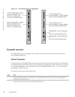
Step Task (continued) Note: Terminal settings on the console port cannot be changed in the software and are set as follows: • 9600 baud rate • No parity • 8 data bits • 1 stop bit • No flow control External Serial Port with a USB Connector Table 4-1 lists the pin assignments. Table 4-1. Pin Assignments USB Pin Number Pin 1 Pin 2 Pin 3 Pin 4 Pin 5, 6 RxD Signal Name RTS RX TX CTS GND Chassis GND Boot Process After you follow the instructions in the Installation Procedure in the Getting Started Guide, the Aggregator boots up. The Aggregator with FTOS version 8.3.17.0 requires boot flash version 4.0.1.0 and boot selector version 4.0.0.0. Figure 4-3 through Figure 4-7 show the completed boot process. Getting Started | 23
-
 1
1 -
2
-
3
-
4
-
5
-
6
-
7
-
8
-
9
-
10
-
11
-
12
-
13
-
14
-
15
-
16
-
17
-
18
-
19
-
20
-
21
-
22
-
23
-
24
-
25
-
26
-
27
-
28
-
29
-
30
-
31
-
 32
32 -
 33
33 -
 34
34 -
 35
35 -
 36
36 -
 37
37 -
 38
38 -
 39
39 -
 40
40 -
 41
41 -
 42
42 -
43
-
44
-
45
-
46
-
47
-
48
-
49
-
50
-
51
-
52
-
53
-
54
-
55
-
56
-
57
-
58
-
59
-
60
-
61
-
62
-
63
-
64
-
65
-
66
-
67
-
68
-
69
-
70
-
71
-
72
-
73
-
74
-
75
-
76
-
77
-
78
-
79
-
80
-
81
-
82
-
83
-
84
-
85
-
86
-
87
-
88
-
89
-
90
-
91
-
92
-
93
-
94
-
95
-
96
-
97
-
98
-
99
-
100
-
101
-
102
-
103
-
104
-
105
-
106
-
107
-
108
-
109
-
110
-
111
-
112
-
113
-
114
-
115
-
116
-
117
-
118
-
119
-
120
-
121
-
122
-
123
-
124
-
125
-
126
-
127
-
128
-
129
-
130
-
131
-
132
-
133
-
134
-
135
-
136
-
137
-
138
-
139
-
140
-
141
-
142
-
143
-
144
-
145
-
146
-
147
-
148
-
149
-
150
-
151
-
152
-
153
-
154
-
155
-
156
-
157
-
158
-
159
-
160
-
161
-
162
-
163
-
164
-
165
-
166
-
167
-
168
-
169
-
170
-
171
-
172
-
173
-
174
-
175
-
176
-
177
-
178
-
179
-
180
-
181
-
182
-
183
-
184
-
185
-
186
-
187
-
188
-
189
-
190
-
191
-
192
-
193
-
194
-
195
-
196
-
197
-
198
-
199
-
200
-
201
-
202
-
203
-
204
-
205
-
206
-
207
-
208
-
209
-
210
-
211
-
212
-
213
-
214
-
215
-
216
-
217
-
218
-
219
-
220
-
221
-
222
-
223
-
224
-
225
-
226
-
227
-
228
-
229
-
230
-
231
-
232
-
233
-
234
-
235
-
236
-
237
-
238
-
239
-
240
-
241
-
242
-
243
-
244
-
245
-
246
-
247
-
248
-
249
-
250
-
251
-
252
-
253
-
254
-
255
-
256
-
257
-
258
-
259
-
260
-
261
-
262
-
263
-
264
-
265
-
266
-
267
-
268
-
269
-
270
-
271
-
272
-
273
-
274
-
275
-
276
-
277
-
278
-
279
-
280
-
281
-
282
-
283
-
284
-
285
-
286
-
287
-
288
-
289
-
290
 |
 |

Getting Started
|
23
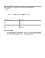
External Serial Port with a USB Connector
Table 4-1
lists the pin assignments.
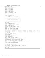
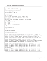
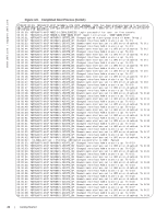
Boot Process
After you follow the instructions in the
Installation Procedure
in the
Getting Started Guide
, the Aggregator
boots up. The Aggregator with FTOS version 8.3.17.0 requires boot flash version 4.0.1.0 and boot selector
version 4.0.0.0.
Figure 4-3
through
Figure 4-7
show the completed boot process.
Note:
Terminal settings on the console port cannot be changed in the software and are set as follows:
•
9600 baud rate
•
No parity
•
8 data bits
•
1 stop bit
•
No flow control
Table 4-1.
Pin Assignments
USB Pin Number
Signal Name
Pin 1
RTS
Pin 2
RX
Pin 3
TX
Pin 4
CTS
Pin 5, 6
GND
RxD
Chassis GND
Step
Task (continued)