HP t310 PCoIP Management Console User Manual - Page 13
Overview
 |
View all HP t310 manuals
Add to My Manuals
Save this manual to your list of manuals |
Page 13 highlights
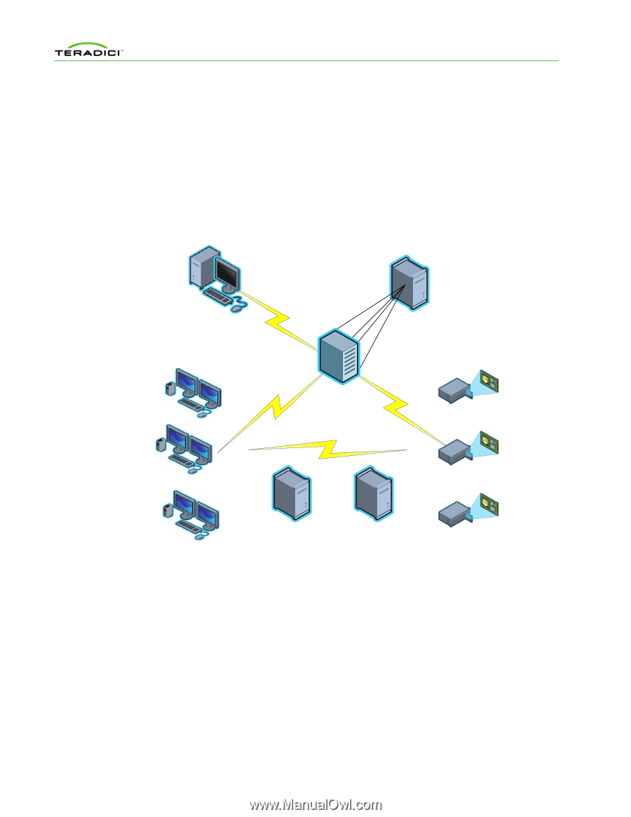
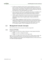
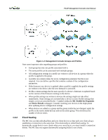
PCoIP Management Console User Manual 1 Overview This section describes the components found in a typical PCoIP deployment. 1.1 PCoIP Deployment Components Figure 1-1 shows the recommended components found in a PCoIP deployment where individual host and zero client devices are statically grouped together (peered). It shows the MC used for peering and configuration. The figure does not show a connection broker, which is required when hosts are dynamically assigned to zero clients as users log in. Web browser administering PCoIP MC HTTPS Server running VMware Player Zero Clients PCoIP MC Virtual Machine Control Control PCoIP™ Hosts 1.1.1 DNS Server with DHCP Server with PCoIP MC DNS SRV PCoIP Vendor Class Record Options Figure 1-1: PCoIP Deployment Components Managing PCoIP Devices A PCoIP deployment is made up of one or more PCoIP host and zero client devices. Each device has multiple configuration settings that you can access and control using the following mechanisms: Device Web Interface Although you can configure each device individually via a web-based administration interface, you are encouraged to use the MC (especially as the deployment grows). This ensures that all PCoIP devices are configured uniformly and that the MC database accurately reflects the device configuration settings. For information about the device web interface, see the PCoIP Zero Client and Host Administrator Guide (TER1206003). TER0812002 Issue 9 14
-
 1
1 -
2
-
3
-
4
-
5
-
6
-
7
-
 8
8 -
 9
9 -
 10
10 -
 11
11 -
 12
12 -
 13
13 -
 14
14 -
 15
15 -
 16
16 -
 17
17 -
 18
18 -
19
-
20
-
21
-
22
-
23
-
24
-
25
-
26
-
27
-
28
-
29
-
30
-
31
-
32
-
33
-
34
-
35
-
36
-
37
-
38
-
39
-
40
-
41
-
42
-
43
-
44
-
45
-
46
-
47
-
48
-
49
-
50
-
51
-
52
-
53
-
54
-
55
-
56
-
57
-
58
-
59
-
60
-
61
-
62
-
63
-
64
-
65
-
66
-
67
-
68
-
69
-
70
-
71
-
72
-
73
-
74
-
75
-
76
-
77
-
78
-
79
-
80
-
81
-
82
-
83
-
84
-
85
-
86
-
87
 |
 |