Lexmark C524 User's Guide - Page 127
Installing an optional flash memory or firmware card
 |
View all Lexmark C524 manuals
Add to My Manuals
Save this manual to your list of manuals |
Page 127 highlights
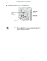
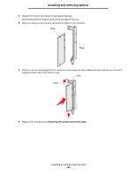
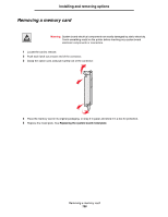
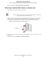
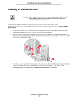
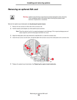
Installing and removing options Installing an optional flash memory or firmware card The system board has two connectors for an optional flash memory or firmware card. Only one of each may be installed, but the connectors are interchangeable. Warning: System board electrical components are easily damaged by static electricity. Touch something metal on the printer before touching any system board electronic components or connectors. CAUTION: If installing a flash or firmware card after setting up the printer, turn the printer off and unplug the power cord before continuing. 1 Access the system board (see Accessing the system board). 2 Unpack the card. Save the packaging materials. Note: Avoid touching the metal pins on the bottom of the card. 3 Holding the card by its sides, align the plastic pins on the card with the holes on the system board. Plastic pins 4 Push the card firmly into place. Metal pins Note: The entire length of the connector on the card must touch and be flush against the system board. Be careful not to damage the connectors. Installing an optional flash memory or firmware card 127
-
 1
1 -
2
-
3
-
4
-
5
-
6
-
7
-
8
-
9
-
10
-
11
-
12
-
13
-
14
-
15
-
16
-
17
-
18
-
19
-
20
-
21
-
22
-
23
-
24
-
25
-
26
-
27
-
28
-
29
-
30
-
31
-
32
-
33
-
34
-
35
-
36
-
37
-
38
-
39
-
40
-
41
-
42
-
43
-
44
-
45
-
46
-
47
-
48
-
49
-
50
-
51
-
52
-
53
-
54
-
55
-
56
-
57
-
58
-
59
-
60
-
61
-
62
-
63
-
64
-
65
-
66
-
67
-
68
-
69
-
70
-
71
-
72
-
73
-
74
-
75
-
76
-
77
-
78
-
79
-
80
-
81
-
82
-
83
-
84
-
85
-
86
-
87
-
88
-
89
-
90
-
91
-
92
-
93
-
94
-
95
-
96
-
97
-
98
-
99
-
100
-
101
-
102
-
103
-
104
-
105
-
106
-
107
-
108
-
109
-
110
-
111
-
112
-
113
-
114
-
115
-
116
-
117
-
118
-
119
-
120
-
121
-
 122
122 -
 123
123 -
 124
124 -
 125
125 -
 126
126 -
 127
127 -
 128
128 -
 129
129 -
 130
130 -
 131
131 -
 132
132 -
133
-
134
-
135
-
136
-
137
-
138
-
139
-
140
-
141
-
142
-
143
-
144
-
145
-
146
 |
 |