Netgear WC7600 Reference Manual - Page 13
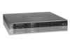
Digital counter, Power LED, Status LED, Fan LED, Stack Master LED, Reset button, USB port, SFP slots
 |
View all Netgear WC7600 manuals
Add to My Manuals
Save this manual to your list of manuals |
Page 13 highlights
ProSAFE Wireless Controller WC7600 From left to right, the wireless controller's front panel shows the following counter, LEDs, button, ports, and slots: • Digital counter. Displays the number of connected access points that are in a healthy state. • From top to bottom: - Power LED - Status LED - Fan LED - Stack Master LED These LEDs are described in Table 1 on page 13. • Reset button. Using a sharp object, press and hold this button for about 10 seconds until the Status LED flashes and the wireless controller returns to factory default settings. If you reset the wireless controller, all configuration settings are lost and the default password is restored. • USB port. Allows for external storage for floor heat maps, which will be supported in a future release. • SFP slots. Two SFP slots for optional 10GE SFP+ or 1G SFP gigabit interface converters (GBICs), each slot with an LED. • Ethernet port. One 10/100/1000 Mbps LAN Ethernet port with an RJ-45 connector, left LED, and right LED. The Ethernet port provides switched N-way, automatic speed negotiating, auto MDI/MDIX technology. • Console port. RS232 port for connecting to an optional console terminal. The port has a DB9 male connector. The default baud rate is 9600 K. The configuration is 8 bits, no parity, and 1 stop bit. The console port is for debugging under guidance of NETGEAR technical support only. The function of each LED is described in the following table: Table 1. LED functions LED Power LED Status Green Off Status LED Yellow Green Description The green Power LED should be lit when the wireless controller is on. If the power LED is not lit when the wireless controller is on, check the connections and check to see if the power outlet is controlled by a wall switch that is turned off (see Power LED Is Not Lit on page 296). The wireless controller is initializing. After approximately two minutes, when the wireless controller has completed its initialization, the Status LED turns green. If the Status LED remains yellow, the initialization has failed (see Status LED Never Turns Off on page 296). The wireless controller has completed its initialization successfully. The Status LED should be steady green during normal operation. Introduction 13
-
 1
1 -
2
-
3
-
4
-
5
-
6
-
7
-
 8
8 -
 9
9 -
 10
10 -
 11
11 -
 12
12 -
 13
13 -
 14
14 -
 15
15 -
 16
16 -
 17
17 -
 18
18 -
19
-
20
-
21
-
22
-
23
-
24
-
25
-
26
-
27
-
28
-
29
-
30
-
31
-
32
-
33
-
34
-
35
-
36
-
37
-
38
-
39
-
40
-
41
-
42
-
43
-
44
-
45
-
46
-
47
-
48
-
49
-
50
-
51
-
52
-
53
-
54
-
55
-
56
-
57
-
58
-
59
-
60
-
61
-
62
-
63
-
64
-
65
-
66
-
67
-
68
-
69
-
70
-
71
-
72
-
73
-
74
-
75
-
76
-
77
-
78
-
79
-
80
-
81
-
82
-
83
-
84
-
85
-
86
-
87
-
88
-
89
-
90
-
91
-
92
-
93
-
94
-
95
-
96
-
97
-
98
-
99
-
100
-
101
-
102
-
103
-
104
-
105
-
106
-
107
-
108
-
109
-
110
-
111
-
112
-
113
-
114
-
115
-
116
-
117
-
118
-
119
-
120
-
121
-
122
-
123
-
124
-
125
-
126
-
127
-
128
-
129
-
130
-
131
-
132
-
133
-
134
-
135
-
136
-
137
-
138
-
139
-
140
-
141
-
142
-
143
-
144
-
145
-
146
-
147
-
148
-
149
-
150
-
151
-
152
-
153
-
154
-
155
-
156
-
157
-
158
-
159
-
160
-
161
-
162
-
163
-
164
-
165
-
166
-
167
-
168
-
169
-
170
-
171
-
172
-
173
-
174
-
175
-
176
-
177
-
178
-
179
-
180
-
181
-
182
-
183
-
184
-
185
-
186
-
187
-
188
-
189
-
190
-
191
-
192
-
193
-
194
-
195
-
196
-
197
-
198
-
199
-
200
-
201
-
202
-
203
-
204
-
205
-
206
-
207
-
208
-
209
-
210
-
211
-
212
-
213
-
214
-
215
-
216
-
217
-
218
-
219
-
220
-
221
-
222
-
223
-
224
-
225
-
226
-
227
-
228
-
229
-
230
-
231
-
232
-
233
-
234
-
235
-
236
-
237
-
238
-
239
-
240
-
241
-
242
-
243
-
244
-
245
-
246
-
247
-
248
-
249
-
250
-
251
-
252
-
253
-
254
-
255
-
256
-
257
-
258
-
259
-
260
-
261
-
262
-
263
-
264
-
265
-
266
-
267
-
268
-
269
-
270
-
271
-
272
-
273
-
274
-
275
-
276
-
277
-
278
-
279
-
280
-
281
-
282
-
283
-
284
-
285
-
286
-
287
-
288
-
289
-
290
-
291
-
292
-
293
-
294
-
295
-
296
-
297
-
298
-
299
-
300
-
301
-
302
-
303
-
304
-
305
-
306
-
307
 |
 |
