Sony PMW200 User Manual (PMW-100 Memory Camcorder Operation Manual for Firmwar - Page 105
Connecting External Devices, Connecting External Monitors and Recording Devices
 |
View all Sony PMW200 manuals
Add to My Manuals
Save this manual to your list of manuals |
Page 105 highlights
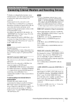
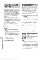
Connecting External Devices Connecting External Monitors and Recording Devices To display recording/playback pictures on an external monitor, select the output signal and use an appropriate cable for the monitor to be connected. Output signal from the camcorder can be recorded when a recording device is connected. Regardless of whether the signal is HD or SD, the same status information and menus can be displayed on the external monitor as those on the LCD monitor/EVF screen. According to the signal fed to the monitor, set "SDI/HDMI/Video Out Super" (page 90) in the VIDEO SET menu to "On." When outputting SD signals in HD Mode, select in advance the output mode (Squeeze, Letterbox, or Edge Crop) with "Down Converter" (page 91) in the VIDEO SET menu. Note SD signals down-converted for output have the following restrictions: Images of 50P/50i/25P are output as PAL signals, those of 59.94P/59.94i/29.97P are output as NTSC signals, and those of 23.98P are output as 2-3 pulled-down NTSC signals. SDI OUT connector (BNC type) The connector is set at the factory to output an HD SDI signal. When you set the camcorder to SD Mode, the connector outputs an SD SDI signal. Set "SDI/HDMI/i.LINK I/O Select" (page 90) in the VIDEO SET menu to "SD SDI & SD HDMI i" to output down-converted SD SDI signals for monitoring, even in HD Mode. Use a commercially available 75-ohm coaxial cable for connection. To start recording on an external device in synchronization With HD SDI signal output selected, synchronized recording is possible by feeding a REC trigger signal to an external recording device connected via the SDI OUT connector. To enable synchronized recording, set "SDI Rec Control" (page 91) in the VIDEO SET menu to "HD SDI Remote I/F." Notes • If you set "SDI/HDMI/i.LINK I/O Select" in the VIDEO SET menu to other than "HD SDI & HD HDMI" or "SD SDI & SD HDMI i" and use the HDMI OUT connector and i.LINK (HDV/DV) connector, no signal will be output from the SDI OUT connector. • When a connected external device does not correspond to a REC trigger signal, the device cannot be operated. HDMI OUT connector (Type A connector) Signal output from this connector is enabled by setting "SDI/HDMI/i.LINK I/O Select" (page 90) in the VIDEO SET menu. In HD Mode, you can select HD HDMI, SD HDMI interlace, or SD HDMI Progressive output. In SD Mode, only an SD HDMI interlace signal can be output. Use a commercially available HDMI cable for connection. VIDEO OUT connector (BNC type) By changing the setting of "SDI/HDMI/i.LINK I/ O Select" (page 90) in the VIDEO SET menu, you can output HD-Y signals in HD Mode or down-converted SD analog composite signals for monitoring in SD Mode. Use a commercially available BNC cable for connection. i.LINK (HDV/DV) connector (IEEE1394, 4pin) Input/output of an HDV or DVCAM stream can be enabled by changing "SDI/HDMI/i.LINK I/O Select" (page 90) in the VIDEO SET menu. To set the input, select "i.LINK" in "Input Source Select" (page 90) in the VIDEO SET menu. A monitor or VTR that supports i.LINK can be connected. For details on i.LINK connection, see "Connecting via i.LINK (FAT only)" (page 108). Connecting External Devices Connecting External Monitors and Recording Devices 105
-
 1
1 -
2
-
3
-
4
-
5
-
6
-
7
-
8
-
9
-
10
-
11
-
12
-
13
-
14
-
15
-
16
-
17
-
18
-
19
-
20
-
21
-
22
-
23
-
24
-
25
-
26
-
27
-
28
-
29
-
30
-
31
-
32
-
33
-
34
-
35
-
36
-
37
-
38
-
39
-
40
-
41
-
42
-
43
-
44
-
45
-
46
-
47
-
48
-
49
-
50
-
51
-
52
-
53
-
54
-
55
-
56
-
57
-
58
-
59
-
60
-
61
-
62
-
63
-
64
-
65
-
66
-
67
-
68
-
69
-
70
-
71
-
72
-
73
-
74
-
75
-
76
-
77
-
78
-
79
-
80
-
81
-
82
-
83
-
84
-
85
-
86
-
87
-
88
-
89
-
90
-
91
-
92
-
93
-
94
-
95
-
96
-
97
-
98
-
99
-
 100
100 -
 101
101 -
 102
102 -
 103
103 -
 104
104 -
 105
105 -
 106
106 -
 107
107 -
 108
108 -
 109
109 -
 110
110 -
111
-
112
-
113
-
114
-
115
-
116
-
117
-
118
-
119
-
120
-
121
-
122
-
123
-
124
-
125
-
126
-
127
-
128
-
129
-
130
-
131
-
132
-
133
-
134
-
135
-
136
-
137
-
138
-
139
-
140
-
141
-
142
 |
 |