Sony PMW200 User Manual (PMW-100 Memory Camcorder Operation Manual for Firmwar - Page 17
Rear connector panel, Controls on the grip, Bottom, i.LINK HDV/DV connector 4-pin, S400 - review
 |
View all Sony PMW200 manuals
Add to My Manuals
Save this manual to your list of manuals |
Page 17 highlights
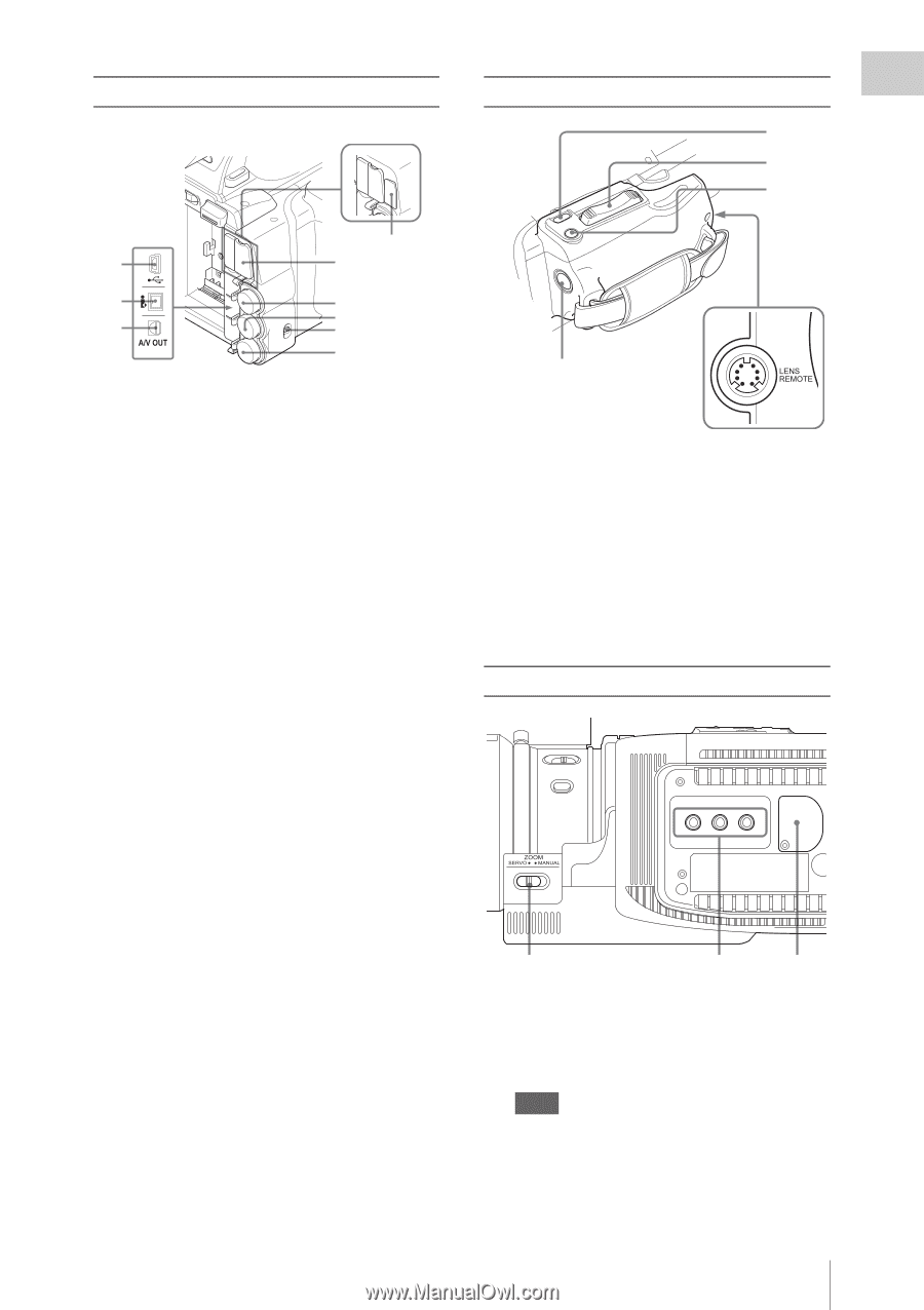
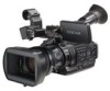
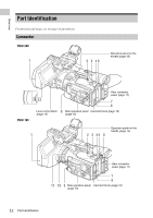
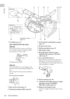
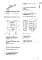
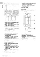
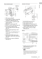
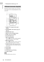
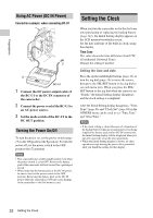
Overview Rear connector panel PMW-200 Behind the cover 1 2 3 9 4 5 6 7 8 1. USB connector (Mini B) 2. i.LINK (HDV/DV) connector (4-pin, S400 conforming to IEEE1394) (page 105) 3. A/V OUT connector (audio/video multi output) (page 106) 4. HDMI OUT connector (page 105) 5. SDI OUT connector (BNC type) (page 105) 6. TC IN (timecode input)/TC OUT (timecode output) connector (BNC type) (page 111) 7. IN/OUT (input/output change) switch (page 111) Set this to IN to select GENLOCK IN, and set this to OUT to select TC OUT and VIDEO OUT. 8. GENLOCK IN/VIDEO OUT (analog video output) connector (BNC type) (page 105, 111) 9. External device connector (PMW-200 only) (page 30) Controls on the grip 1 2 3 4 5 PMW-200 1. REC REVIEW button (page 38) 2. Power zoom lever (page 43) 3. EXPANDED FOCUS button (page 43) 4. LENS REMOTE (lens remote controller) connector (PMW-200 only) (page 43) 5. REC START (start/stop recording) button (page 38) Bottom 1 2 3 1. ZOOM (zoom mode switching) switch (PMW-200 only) (page 43) 2. Tripod receptacles Note Check that the size of the hole matches the screw of the tripod. If they do not match, the camcorder cannot be attached to the tripod securely, and this may lead to the physical injury of the camera operator. Part Identification 17
-
 1
1 -
2
-
3
-
4
-
5
-
6
-
7
-
8
-
9
-
10
-
11
-
 12
12 -
 13
13 -
 14
14 -
 15
15 -
 16
16 -
 17
17 -
 18
18 -
 19
19 -
 20
20 -
 21
21 -
 22
22 -
23
-
24
-
25
-
26
-
27
-
28
-
29
-
30
-
31
-
32
-
33
-
34
-
35
-
36
-
37
-
38
-
39
-
40
-
41
-
42
-
43
-
44
-
45
-
46
-
47
-
48
-
49
-
50
-
51
-
52
-
53
-
54
-
55
-
56
-
57
-
58
-
59
-
60
-
61
-
62
-
63
-
64
-
65
-
66
-
67
-
68
-
69
-
70
-
71
-
72
-
73
-
74
-
75
-
76
-
77
-
78
-
79
-
80
-
81
-
82
-
83
-
84
-
85
-
86
-
87
-
88
-
89
-
90
-
91
-
92
-
93
-
94
-
95
-
96
-
97
-
98
-
99
-
100
-
101
-
102
-
103
-
104
-
105
-
106
-
107
-
108
-
109
-
110
-
111
-
112
-
113
-
114
-
115
-
116
-
117
-
118
-
119
-
120
-
121
-
122
-
123
-
124
-
125
-
126
-
127
-
128
-
129
-
130
-
131
-
132
-
133
-
134
-
135
-
136
-
137
-
138
-
139
-
140
-
141
-
142
 |
 |