Sony PMW200 User Manual (PMW-100 Memory Camcorder Operation Manual for Firmwar - Page 90
VIDEO SET Menu, Menu items, Setting values, Contents
 |
View all Sony PMW200 manuals
Add to My Manuals
Save this manual to your list of manuals |
Page 90 highlights
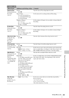
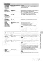
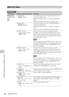
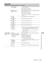
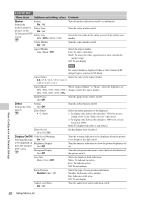
VIDEO SET Menu VIDEO SET Menu items Setting values Contents Input Source Select Setting the input source Camera / i.LINK Select video and audio signal for the input source. Camera: Camera image i.LINK: HDV/DVCAM input via the i.LINK (HDV/DV) connector Notes SDI/HDMI/ i.LINK I/O Select Selecting input/ output signals for the connectors SDI/HDMI/ Video Out Super Setting the character information for each output When using UDF HD Mode HD SDI & HD HDMI SD SDI & SD HDMI i SD HDMI P Off When using FAT HD Mode (HQ) HD SDI & HD HDMI SD SDI & SD HDMI i SD HDMI i & DVCAM SD HDMI P Off When using FAT HD Mode (SP) HD SDI & HD HDMI SD SDI & SD HDMI i HD HDMI & HDV SD HDMI i & HDV SD HDMI P & HDV SD HDMI i & DVCAM Off When using UDF SD Mode SD SDI & SD HDMI i Off When using FAT SD Mode SD SDI & SD HDMI i SD HDMI i & DVCAM Off On / Off • i.LINK is unavailable when using UDF. • DVCAM is for display only and cannot be recorded. HD SDI & HD HDMI: To output HD SDI signals from the SDI OUT connector, and HD HDMI signals from the HDMI OUT connector. SD SDI & SD HDMI i: To output SD SDI signals from the SDI OUT connector, and SD HDMI interlace signals from the HDMI OUT connector. HD HDMI & HDV: To output HD HDMI signals from the HDMI OUT connector, and input/output HDV streams from the i.LINK (HDV/DV) connector. SD HDMI i & HDV: To output SD HDMI interlace signals from the HDMI OUT connector, and input/output HDV streams from the i.LINK (HDV/DV) connector. SD HDMI P & HDV: To output SD HDMI progressive signals from the HDMI OUT connector, and input/output HDV streams from the i.LINK (HDV/DV) connector. SD HDMI i & DVCAM: To output SD HDMI interlace signals from the HDMI OUT connector, and input/output DVCAM streams from the i.LINK (HDV/DV) connector. SD HDMI P: To output SD HDMI progressive signals from the HDMI OUT connector. Off: There is no output from the SDI/HDMI/i.LINK connectors. Notes • Signals are not output from the SDI OUT connector when this is set to other than an HD SDI or SD SDI setting. • Slow & Quick Motion mode cannot be used when this is set to input/output DVCAM streams. Set whether to add the menus and status indications of the LCD monitor/EVF screen to the output of the SDI OUT, HDMI OUT, VIDEO OUT, and A/V OUT connectors. Note On the thumbnail, EXPAND CLIP and SHOT MARK screens, the menus and status indications on the LCD monitor/EVF screen are displayed regardless of the setting of this item. Menu Configuration and Detailed Settings 90 Setup Menu List
-
 1
1 -
2
-
3
-
4
-
5
-
6
-
7
-
8
-
9
-
10
-
11
-
12
-
13
-
14
-
15
-
16
-
17
-
18
-
19
-
20
-
21
-
22
-
23
-
24
-
25
-
26
-
27
-
28
-
29
-
30
-
31
-
32
-
33
-
34
-
35
-
36
-
37
-
38
-
39
-
40
-
41
-
42
-
43
-
44
-
45
-
46
-
47
-
48
-
49
-
50
-
51
-
52
-
53
-
54
-
55
-
56
-
57
-
58
-
59
-
60
-
61
-
62
-
63
-
64
-
65
-
66
-
67
-
68
-
69
-
70
-
71
-
72
-
73
-
74
-
75
-
76
-
77
-
78
-
79
-
80
-
81
-
82
-
83
-
84
-
 85
85 -
 86
86 -
 87
87 -
 88
88 -
 89
89 -
 90
90 -
 91
91 -
 92
92 -
 93
93 -
 94
94 -
 95
95 -
96
-
97
-
98
-
99
-
100
-
101
-
102
-
103
-
104
-
105
-
106
-
107
-
108
-
109
-
110
-
111
-
112
-
113
-
114
-
115
-
116
-
117
-
118
-
119
-
120
-
121
-
122
-
123
-
124
-
125
-
126
-
127
-
128
-
129
-
130
-
131
-
132
-
133
-
134
-
135
-
136
-
137
-
138
-
139
-
140
-
141
-
142
 |
 |