D-Link DGS-1510-28P User Manual - Page 109
Voice VLAN LLDP-MED Device, Spanning Tree
 |
View all D-Link DGS-1510-28P manuals
Add to My Manuals
Save this manual to your list of manuals |
Page 109 highlights
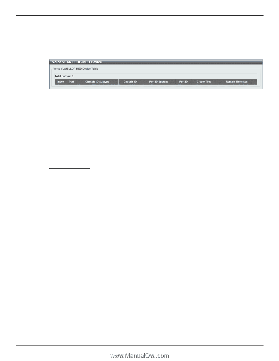
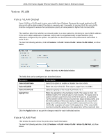
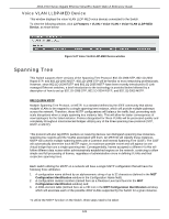
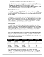
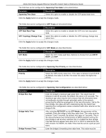
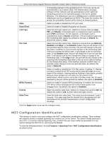
DGS-1510 Series Gigabit Ethernet SmartPro Switch Web UI Reference Guide Voice VLAN LLDP-MED Device This window displays the voice VLAN LLDP-MED voice devices connected to the Switch. To view the following window, click L2 Features > VLAN > Voice VLAN > Voice VLAN LLDP-MED Device, as show below: Figure 5-27 Voice VLAN LLDP-MED Device window Spanning Tree This Switch supports three versions of the Spanning Tree Protocol: 802.1D-1998 STP, 802.1D-2004 Rapid STP, and 802.1Q-2005 MSTP. 802.1D-1998 STP will be familiar to most networking professionals. However, since 802.1D-2004 RSTP and 802.1Q-2005 MSTP have been recently introduced to D-Link managed Ethernet switches, a brief introduction to the technology is provided below followed by a description of how to set up 802.1D-1998 STP, 802.1D-2004 RSTP, and 802.1Q-2005 MSTP. 802.1Q-2005 MSTP Multiple Spanning Tree Protocol, or MSTP, is a standard defined by the IEEE community that allows multiple VLANs to be mapped to a single spanning tree instance, which will provide multiple pathways across the network. Therefore, these MSTP configurations will balance the traffic load, preventing wide scale disruptions when a single spanning tree instance fails. This will allow for faster convergences of new topologies for the failed instance. Frames designated for these VLANs will be processed quickly and completely throughout interconnected bridges utilizing any of the three spanning tree protocols (STP, RSTP or MSTP). This protocol will also tag BPDU packets so receiving devices can distinguish spanning tree instances, spanning tree regions and the VLANs associated with them. An MSTI ID will classify these instances. MSTP will connect multiple spanning trees with a Common and Internal Spanning Tree (CIST). The CIST will automatically determine each MSTP region, its maximum possible extent and will appear as one virtual bridge that runs a single spanning tree. Consequentially, frames assigned to different VLANs will follow different data routes within administratively established regions on the network, continuing to allow simple and full processing of frames, regardless of administrative errors in defining VLANs and their respective spanning trees. Each switch utilizing the MSTP on a network will have a single MSTP configuration that will have the following three attributes: 1. A configuration name defined by an alphanumeric string of up to 32 characters (defined in the MST Configuration Identification window in the Configuration Name field). 2. A configuration revision number (named here as a Revision Level and found in the MST Configuration Identification window) and; 3. A 4094-element table (defined here as a VID List in the MST Configuration Identification window), which will associate each of the possible 4094 VLANs supported by the Switch for a given instance. To utilize the MSTP function on the Switch, three steps need to be taken: 101
-
 1
1 -
2
-
3
-
4
-
5
-
6
-
7
-
8
-
9
-
10
-
11
-
12
-
13
-
14
-
15
-
16
-
17
-
18
-
19
-
20
-
21
-
22
-
23
-
24
-
25
-
26
-
27
-
28
-
29
-
30
-
31
-
32
-
33
-
34
-
35
-
36
-
37
-
38
-
39
-
40
-
41
-
42
-
43
-
44
-
45
-
46
-
47
-
48
-
49
-
50
-
51
-
52
-
53
-
54
-
55
-
56
-
57
-
58
-
59
-
60
-
61
-
62
-
63
-
64
-
65
-
66
-
67
-
68
-
69
-
70
-
71
-
72
-
73
-
74
-
75
-
76
-
77
-
78
-
79
-
80
-
81
-
82
-
83
-
84
-
85
-
86
-
87
-
88
-
89
-
90
-
91
-
92
-
93
-
94
-
95
-
96
-
97
-
98
-
99
-
100
-
101
-
102
-
103
-
 104
104 -
 105
105 -
 106
106 -
 107
107 -
 108
108 -
 109
109 -
 110
110 -
 111
111 -
 112
112 -
 113
113 -
 114
114 -
115
-
116
-
117
-
118
-
119
-
120
-
121
-
122
-
123
-
124
-
125
-
126
-
127
-
128
-
129
-
130
-
131
-
132
-
133
-
134
-
135
-
136
-
137
-
138
-
139
-
140
-
141
-
142
-
143
-
144
-
145
-
146
-
147
-
148
-
149
-
150
-
151
-
152
-
153
-
154
-
155
-
156
-
157
-
158
-
159
-
160
-
161
-
162
-
163
-
164
-
165
-
166
-
167
-
168
-
169
-
170
-
171
-
172
-
173
-
174
-
175
-
176
-
177
-
178
-
179
-
180
-
181
-
182
-
183
-
184
-
185
-
186
-
187
-
188
-
189
-
190
-
191
-
192
-
193
-
194
-
195
-
196
-
197
-
198
-
199
-
200
-
201
-
202
-
203
-
204
-
205
-
206
-
207
-
208
-
209
-
210
-
211
-
212
-
213
-
214
-
215
-
216
-
217
-
218
-
219
-
220
-
221
-
222
-
223
-
224
-
225
-
226
-
227
-
228
-
229
-
230
-
231
-
232
-
233
-
234
-
235
-
236
-
237
-
238
-
239
-
240
-
241
-
242
-
243
-
244
-
245
-
246
-
247
-
248
-
249
-
250
-
251
-
252
-
253
-
254
-
255
-
256
-
257
-
258
-
259
-
260
-
261
-
262
-
263
-
264
-
265
-
266
-
267
-
268
-
269
-
270
-
271
-
272
-
273
-
274
-
275
-
276
-
277
-
278
-
279
-
280
-
281
-
282
-
283
-
284
-
285
-
286
-
287
-
288
-
289
-
290
-
291
-
292
-
293
-
294
-
295
-
296
-
297
-
298
-
299
-
300
-
301
-
302
-
303
-
304
-
305
-
306
-
307
-
308
-
309
-
310
-
311
-
312
-
313
-
314
-
315
-
316
-
317
-
318
-
319
-
320
-
321
-
322
-
323
-
324
-
325
-
326
-
327
-
328
-
329
-
330
-
331
-
332
-
333
-
334
-
335
-
336
-
337
-
338
-
339
-
340
-
341
-
342
-
343
-
344
-
345
-
346
-
347
-
348
-
349
-
350
-
351
-
352
-
353
-
354
-
355
-
356
-
357
-
358
-
359
-
360
-
361
-
362
-
363
-
364
-
365
-
366
-
367
-
368
-
369
-
370
-
371
-
372
-
373
-
374
-
375
-
376
-
377
-
378
-
379
-
380
-
381
-
382
-
383
-
384
-
385
-
386
-
387
-
388
-
389
-
390
-
391
-
392
-
393
-
394
-
395
-
396
-
397
-
398
-
399
-
400
-
401
-
402
-
403
-
404
-
405
-
406
-
407
-
408
-
409
-
410
-
411
-
412
-
413
-
414
-
415
-
416
-
417
-
418
-
419
-
420
-
421
-
422
-
423
-
424
-
425
-
426
-
427
-
428
-
429
-
430
 |
 |