D-Link DGS-1510-28P User Manual - Page 73
Primary Master, Backup Master, Slave
 |
View all D-Link DGS-1510-28P manuals
Add to My Manuals
Save this manual to your list of manuals |
Page 73 highlights
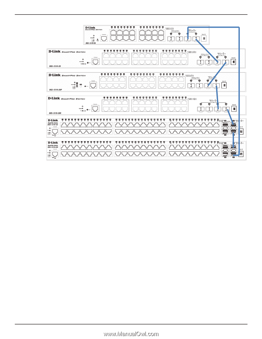
DGS-1510 Series Gigabit Ethernet SmartPro Switch Web UI Reference Guide Figure 4-46 Switches stacked in a Duplex Ring Within each of these topologies, each switch plays a role in the Switch stack. These roles can be set by the user per individual Switch, or if desired, can be automatically determined by the Switch stack. Three possible roles exist when stacking with the Switch. Primary Master - The Primary Master is the leader of the stack. It will maintain normal operations, monitor operations and the running topology of the Stack. This switch will also assign Stack Unit IDs, synchronize configurations and transmit commands to remaining switches in the switch stack. The Primary Master can be manually set by assigning this Switch the highest priority (a lower number denotes a higher priority) before physically assembling the stack, or it can be determined automatically by the stack through an election process which determines the lowest MAC address and then will assign that switch as the Primary Master, if all priorities are the same. The Primary master are physically displayed by the seven segment LED to the far right on the front panel of the switch where this LED will flash between its given Box ID and 'H'. Backup Master - The Backup Master is the backup to the Primary Master, and will take over the functions of the Primary Master if the Primary Master fails or is removed from the Stack. It also monitors the status of neighboring switches in the stack, will perform commands assigned to it by the Primary Master and will monitor the running status of the Primary Master. The Backup Master can be set by the user by assigning this Switch the second highest priority before physically assembling the stack, or it can be determined automatically by the stack through an election process which determines the second lowest MAC address and then will assign that switch as the Backup Master, if all priorities are the same. The Backup master are physically displayed by the seven segment LED to the far right on the front panel of the switch where this LED will flash between its given Box ID and 'h'. Slave - Slave switches constitute the rest of the switch stack and although not Primary or Backup Masters, they can be placed into these roles when these other two roles fail or are removed from the stack. Slave switches perform operations requested by the master, monitor the status of neighbor switches in the stack and the stack topology and adhere to the Backup Master's commands once it becomes a Primary Master. Slave switches will do a self-check to determine if it is to become the Backup 65
-
 1
1 -
2
-
3
-
4
-
5
-
6
-
7
-
8
-
9
-
10
-
11
-
12
-
13
-
14
-
15
-
16
-
17
-
18
-
19
-
20
-
21
-
22
-
23
-
24
-
25
-
26
-
27
-
28
-
29
-
30
-
31
-
32
-
33
-
34
-
35
-
36
-
37
-
38
-
39
-
40
-
41
-
42
-
43
-
44
-
45
-
46
-
47
-
48
-
49
-
50
-
51
-
52
-
53
-
54
-
55
-
56
-
57
-
58
-
59
-
60
-
61
-
62
-
63
-
64
-
65
-
66
-
67
-
 68
68 -
 69
69 -
 70
70 -
 71
71 -
 72
72 -
 73
73 -
 74
74 -
 75
75 -
 76
76 -
 77
77 -
 78
78 -
79
-
80
-
81
-
82
-
83
-
84
-
85
-
86
-
87
-
88
-
89
-
90
-
91
-
92
-
93
-
94
-
95
-
96
-
97
-
98
-
99
-
100
-
101
-
102
-
103
-
104
-
105
-
106
-
107
-
108
-
109
-
110
-
111
-
112
-
113
-
114
-
115
-
116
-
117
-
118
-
119
-
120
-
121
-
122
-
123
-
124
-
125
-
126
-
127
-
128
-
129
-
130
-
131
-
132
-
133
-
134
-
135
-
136
-
137
-
138
-
139
-
140
-
141
-
142
-
143
-
144
-
145
-
146
-
147
-
148
-
149
-
150
-
151
-
152
-
153
-
154
-
155
-
156
-
157
-
158
-
159
-
160
-
161
-
162
-
163
-
164
-
165
-
166
-
167
-
168
-
169
-
170
-
171
-
172
-
173
-
174
-
175
-
176
-
177
-
178
-
179
-
180
-
181
-
182
-
183
-
184
-
185
-
186
-
187
-
188
-
189
-
190
-
191
-
192
-
193
-
194
-
195
-
196
-
197
-
198
-
199
-
200
-
201
-
202
-
203
-
204
-
205
-
206
-
207
-
208
-
209
-
210
-
211
-
212
-
213
-
214
-
215
-
216
-
217
-
218
-
219
-
220
-
221
-
222
-
223
-
224
-
225
-
226
-
227
-
228
-
229
-
230
-
231
-
232
-
233
-
234
-
235
-
236
-
237
-
238
-
239
-
240
-
241
-
242
-
243
-
244
-
245
-
246
-
247
-
248
-
249
-
250
-
251
-
252
-
253
-
254
-
255
-
256
-
257
-
258
-
259
-
260
-
261
-
262
-
263
-
264
-
265
-
266
-
267
-
268
-
269
-
270
-
271
-
272
-
273
-
274
-
275
-
276
-
277
-
278
-
279
-
280
-
281
-
282
-
283
-
284
-
285
-
286
-
287
-
288
-
289
-
290
-
291
-
292
-
293
-
294
-
295
-
296
-
297
-
298
-
299
-
300
-
301
-
302
-
303
-
304
-
305
-
306
-
307
-
308
-
309
-
310
-
311
-
312
-
313
-
314
-
315
-
316
-
317
-
318
-
319
-
320
-
321
-
322
-
323
-
324
-
325
-
326
-
327
-
328
-
329
-
330
-
331
-
332
-
333
-
334
-
335
-
336
-
337
-
338
-
339
-
340
-
341
-
342
-
343
-
344
-
345
-
346
-
347
-
348
-
349
-
350
-
351
-
352
-
353
-
354
-
355
-
356
-
357
-
358
-
359
-
360
-
361
-
362
-
363
-
364
-
365
-
366
-
367
-
368
-
369
-
370
-
371
-
372
-
373
-
374
-
375
-
376
-
377
-
378
-
379
-
380
-
381
-
382
-
383
-
384
-
385
-
386
-
387
-
388
-
389
-
390
-
391
-
392
-
393
-
394
-
395
-
396
-
397
-
398
-
399
-
400
-
401
-
402
-
403
-
404
-
405
-
406
-
407
-
408
-
409
-
410
-
411
-
412
-
413
-
414
-
415
-
416
-
417
-
418
-
419
-
420
-
421
-
422
-
423
-
424
-
425
-
426
-
427
-
428
-
429
-
430
 |
 |