D-Link DGS-1510-28P User Manual - Page 345
Safeguard Engine, MAC Address, Protocol, DOT1X, Apply, Clear by Port, Clear by MAC, Clear by Protocol
 |
View all D-Link DGS-1510-28P manuals
Add to My Manuals
Save this manual to your list of manuals |
Page 345 highlights
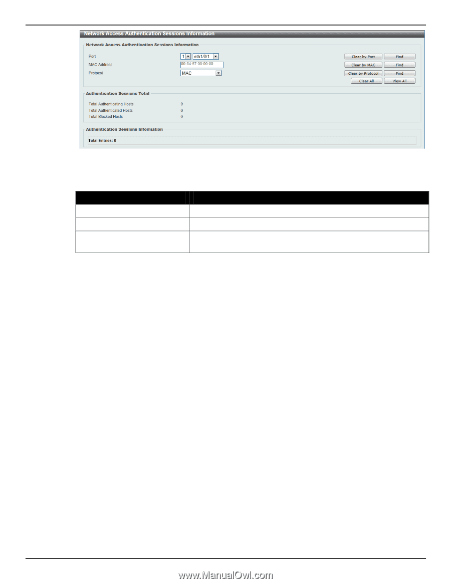
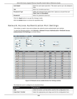
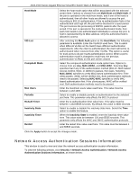
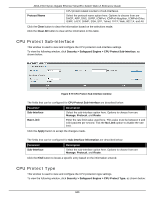
DGS-1510 Series Gigabit Ethernet SmartPro Switch Web UI Reference Guide Figure 9-76 Network Access Authentication Sessions Information window The fields that can be configured are described below: Parameter Port MAC Address Protocol Description Select the appropriate switch unit and port used for the query here. Enter the MAC address used here. Select the protocol option used here. Options to choose from are MAC, WAC, JWAC, and DOT1X. Click the Apply button to accept the changes made. Click the Clear by Port button to the clear the information based on the port selected. Click the Clear by MAC button to the clear the information based on the MAC address entered. Click the Clear by Protocol button to the clear the information based on the protocol selected. Click the Clear All button to clear all the information in this table. Click the Find button to locate a specific entry based on the information entered. Click the View All button to locate and display all the entries. Safeguard Engine Periodically, malicious hosts on the network will attack the Switch by utilizing packet flooding (ARP Storm) or other methods. These attacks may increase the switch's CPU load beyond its capability. To alleviate this problem, the Safeguard Engine function was added to the Switch's software. The Safeguard Engine can help the overall operability of the Switch by minimizing the workload of the Switch while the attack is ongoing, thus making it capable to forward essential packets over its network in a limited bandwidth. If the CPU load rises above the rising threshold value, the Safeguard Engine function will be activated and the Switch will enter the exhausted mode. In the exhausted mode, the Switch will limit the bandwidth available for ARP and broadcast IP packets. If the CPU load falls below the falling threshold value, the Safeguard Engine will be deactivated and the Switch will exit the exhausted mode and enter the normal mode. Packets that are destined to the CPU can be classified into three groups. These groups, otherwise known as sub-interfaces, are logical interfaces that the CPU will use to identify certain types of traffic. The three groups are Protocol, Manage, and Route. Generally, the Protocol group should receive the highest priority when the Switch's CPU processes received packets and the Route group should receive the lowest priority as the Switch's CPU usually does get involved in the processing of routing packets. In the Protocol group, packets are protocol control packets identified by the router. In the Manage group, 337
-
 1
1 -
2
-
3
-
4
-
5
-
6
-
7
-
8
-
9
-
10
-
11
-
12
-
13
-
14
-
15
-
16
-
17
-
18
-
19
-
20
-
21
-
22
-
23
-
24
-
25
-
26
-
27
-
28
-
29
-
30
-
31
-
32
-
33
-
34
-
35
-
36
-
37
-
38
-
39
-
40
-
41
-
42
-
43
-
44
-
45
-
46
-
47
-
48
-
49
-
50
-
51
-
52
-
53
-
54
-
55
-
56
-
57
-
58
-
59
-
60
-
61
-
62
-
63
-
64
-
65
-
66
-
67
-
68
-
69
-
70
-
71
-
72
-
73
-
74
-
75
-
76
-
77
-
78
-
79
-
80
-
81
-
82
-
83
-
84
-
85
-
86
-
87
-
88
-
89
-
90
-
91
-
92
-
93
-
94
-
95
-
96
-
97
-
98
-
99
-
100
-
101
-
102
-
103
-
104
-
105
-
106
-
107
-
108
-
109
-
110
-
111
-
112
-
113
-
114
-
115
-
116
-
117
-
118
-
119
-
120
-
121
-
122
-
123
-
124
-
125
-
126
-
127
-
128
-
129
-
130
-
131
-
132
-
133
-
134
-
135
-
136
-
137
-
138
-
139
-
140
-
141
-
142
-
143
-
144
-
145
-
146
-
147
-
148
-
149
-
150
-
151
-
152
-
153
-
154
-
155
-
156
-
157
-
158
-
159
-
160
-
161
-
162
-
163
-
164
-
165
-
166
-
167
-
168
-
169
-
170
-
171
-
172
-
173
-
174
-
175
-
176
-
177
-
178
-
179
-
180
-
181
-
182
-
183
-
184
-
185
-
186
-
187
-
188
-
189
-
190
-
191
-
192
-
193
-
194
-
195
-
196
-
197
-
198
-
199
-
200
-
201
-
202
-
203
-
204
-
205
-
206
-
207
-
208
-
209
-
210
-
211
-
212
-
213
-
214
-
215
-
216
-
217
-
218
-
219
-
220
-
221
-
222
-
223
-
224
-
225
-
226
-
227
-
228
-
229
-
230
-
231
-
232
-
233
-
234
-
235
-
236
-
237
-
238
-
239
-
240
-
241
-
242
-
243
-
244
-
245
-
246
-
247
-
248
-
249
-
250
-
251
-
252
-
253
-
254
-
255
-
256
-
257
-
258
-
259
-
260
-
261
-
262
-
263
-
264
-
265
-
266
-
267
-
268
-
269
-
270
-
271
-
272
-
273
-
274
-
275
-
276
-
277
-
278
-
279
-
280
-
281
-
282
-
283
-
284
-
285
-
286
-
287
-
288
-
289
-
290
-
291
-
292
-
293
-
294
-
295
-
296
-
297
-
298
-
299
-
300
-
301
-
302
-
303
-
304
-
305
-
306
-
307
-
308
-
309
-
310
-
311
-
312
-
313
-
314
-
315
-
316
-
317
-
318
-
319
-
320
-
321
-
322
-
323
-
324
-
325
-
326
-
327
-
328
-
329
-
330
-
331
-
332
-
333
-
334
-
335
-
336
-
337
-
338
-
339
-
 340
340 -
 341
341 -
 342
342 -
 343
343 -
 344
344 -
 345
345 -
 346
346 -
 347
347 -
 348
348 -
 349
349 -
 350
350 -
351
-
352
-
353
-
354
-
355
-
356
-
357
-
358
-
359
-
360
-
361
-
362
-
363
-
364
-
365
-
366
-
367
-
368
-
369
-
370
-
371
-
372
-
373
-
374
-
375
-
376
-
377
-
378
-
379
-
380
-
381
-
382
-
383
-
384
-
385
-
386
-
387
-
388
-
389
-
390
-
391
-
392
-
393
-
394
-
395
-
396
-
397
-
398
-
399
-
400
-
401
-
402
-
403
-
404
-
405
-
406
-
407
-
408
-
409
-
410
-
411
-
412
-
413
-
414
-
415
-
416
-
417
-
418
-
419
-
420
-
421
-
422
-
423
-
424
-
425
-
426
-
427
-
428
-
429
-
430
 |
 |