Dell PowerEdge R830 Owners Manual - Page 12
LCD panel, Table 1. Front panel features 2.5-inch hard drive chassis continued
 |
View all Dell PowerEdge R830 manuals
Add to My Manuals
Save this manual to your list of manuals |
Page 12 highlights
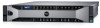
Table 1. Front panel features (2.5-inch hard drive chassis) (continued) Item Indicator, button, or connector Icon Description 6 Information tag Displays system information such as service tag, NIC, and MAC address. NOTE: The information tag is a slide-out label panel. 7 LCD panel 8 Hard drives 9 vFlash media card slot Displays system ID, status information, and system error messages. For more information, see the LCD panel section. For information about the supported hard drives, see the Technical specifications section. Use the vFlash media card slot to insert a vFlash media card. 10 USB 2.0 port 11 USB management port/iDRAC Direct 12 Optical drive (optional) Use the USB 2.0 port to connect USB devices to the system. This port is 4-pin, USB 2.0 compliant. Use the USB management port/iDRAC Direct port to connect USB devices to the system or provide access to the iDRAC Direct features. The USB management port is USB 2.0 compliant. For more information, see the Integrated Dell Remote Access Controller User's Guide at Dell.com/ idracmanuals. For information about the supported optical drive, see the Technical specifications section. Related references Technical specifications on page 24 Safety instructions on page 63 Related tasks Removing the system cover on page 66 LCD panel The LCD panel of your system provides system information, status, and error messages to indicate if the system is functioning correctly or if the system needs attention. For more information about error messages, see the Dell Event and Error Messages Reference Guide at Dell.com/openmanagemanuals >OpenManage software. ● The LCD backlight turns blue during normal operating conditions. ● When the system needs attention, the LCD turns amber, and displays an error code followed by descriptive text. NOTE: If the system is connected to a power source and an error is detected, the LCD turns amber regardless of whether the system is turned on or off. ● The LCD backlight is turned off when the system is in standby mode and can be turned on by pressing either the Select, Left, or Right button on the LCD panel. ● The LCD backlight remains off if LCD messaging is turned off using the iDRAC utility, the LCD panel, or other tools. Figure 4. LCD panel features 12 Dell PowerEdge R830 overview
-
 1
1 -
2
-
3
-
4
-
5
-
6
-
 7
7 -
 8
8 -
 9
9 -
 10
10 -
 11
11 -
 12
12 -
 13
13 -
 14
14 -
 15
15 -
 16
16 -
 17
17 -
18
-
19
-
20
-
21
-
22
-
23
-
24
-
25
-
26
-
27
-
28
-
29
-
30
-
31
-
32
-
33
-
34
-
35
-
36
-
37
-
38
-
39
-
40
-
41
-
42
-
43
-
44
-
45
-
46
-
47
-
48
-
49
-
50
-
51
-
52
-
53
-
54
-
55
-
56
-
57
-
58
-
59
-
60
-
61
-
62
-
63
-
64
-
65
-
66
-
67
-
68
-
69
-
70
-
71
-
72
-
73
-
74
-
75
-
76
-
77
-
78
-
79
-
80
-
81
-
82
-
83
-
84
-
85
-
86
-
87
-
88
-
89
-
90
-
91
-
92
-
93
-
94
-
95
-
96
-
97
-
98
-
99
-
100
-
101
-
102
-
103
-
104
-
105
-
106
-
107
-
108
-
109
-
110
-
111
-
112
-
113
-
114
-
115
-
116
-
117
-
118
-
119
-
120
-
121
-
122
-
123
-
124
-
125
-
126
-
127
-
128
-
129
-
130
-
131
-
132
-
133
-
134
-
135
-
136
-
137
-
138
-
139
-
140
-
141
-
142
-
143
-
144
-
145
-
146
-
147
-
148
-
149
-
150
-
151
-
152
-
153
-
154
-
155
-
156
-
157
-
158
-
159
-
160
-
161
-
162
-
163
-
164
-
165
-
166
-
167
-
168
-
169
-
170
-
171
-
172
-
173
-
174
-
175
-
176
-
177
-
178
-
179
-
180
-
181
-
182
-
183
-
184
-
185
-
186
-
187
-
188
-
189
 |
 |
