Dell PowerEdge R830 Owners Manual - Page 68
Steps, Next steps, Related references, Related tasks, Installing the system cover
 |
View all Dell PowerEdge R830 manuals
Add to My Manuals
Save this manual to your list of manuals |
Page 68 highlights
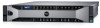
3. Ensure that all internal cables are connected and placed out of the way, and no tools or extra parts are left inside the system. Steps 1. Align the slots on the system cover with the tabs on the chassis. 2. Push the system cover latch down. The system cover slides forward and the slots on the system cover engage with the tabs on the chassis. The system cover latch locks into place when the system cover is completely engaged with the tabs on the chassis. 3. Rotate the latch release lock clockwise to the locked position. Figure 14. Installing the system cover a. system cover b. latch c. latch release lock Next steps 1. If removed, install the front bezel. 2. Reconnect the peripherals and connect the system to the electrical outlet. 3. Turn on the system, including any attached peripherals. 4. Follow the procedure listed in the After working inside your system section. Related references Safety instructions on page 63 Related tasks Removing the optional front bezel on page 65 68 Installing and removing system components
-
 1
1 -
2
-
3
-
4
-
5
-
6
-
7
-
8
-
9
-
10
-
11
-
12
-
13
-
14
-
15
-
16
-
17
-
18
-
19
-
20
-
21
-
22
-
23
-
24
-
25
-
26
-
27
-
28
-
29
-
30
-
31
-
32
-
33
-
34
-
35
-
36
-
37
-
38
-
39
-
40
-
41
-
42
-
43
-
44
-
45
-
46
-
47
-
48
-
49
-
50
-
51
-
52
-
53
-
54
-
55
-
56
-
57
-
58
-
59
-
60
-
61
-
62
-
 63
63 -
 64
64 -
 65
65 -
 66
66 -
 67
67 -
 68
68 -
 69
69 -
 70
70 -
 71
71 -
 72
72 -
 73
73 -
74
-
75
-
76
-
77
-
78
-
79
-
80
-
81
-
82
-
83
-
84
-
85
-
86
-
87
-
88
-
89
-
90
-
91
-
92
-
93
-
94
-
95
-
96
-
97
-
98
-
99
-
100
-
101
-
102
-
103
-
104
-
105
-
106
-
107
-
108
-
109
-
110
-
111
-
112
-
113
-
114
-
115
-
116
-
117
-
118
-
119
-
120
-
121
-
122
-
123
-
124
-
125
-
126
-
127
-
128
-
129
-
130
-
131
-
132
-
133
-
134
-
135
-
136
-
137
-
138
-
139
-
140
-
141
-
142
-
143
-
144
-
145
-
146
-
147
-
148
-
149
-
150
-
151
-
152
-
153
-
154
-
155
-
156
-
157
-
158
-
159
-
160
-
161
-
162
-
163
-
164
-
165
-
166
-
167
-
168
-
169
-
170
-
171
-
172
-
173
-
174
-
175
-
176
-
177
-
178
-
179
-
180
-
181
-
182
-
183
-
184
-
185
-
186
-
187
-
188
-
189
 |
 |
