Dell PowerEdge R830 Owners Manual - Page 131
Removing the optional internal dual SD module, Table 35. IDSDM indicator codes
 |
View all Dell PowerEdge R830 manuals
Add to My Manuals
Save this manual to your list of manuals |
Page 131 highlights
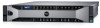
Related references Safety instructions on page 63 Related tasks Before working inside your system on page 64 After working inside your system on page 64 Removing the optional internal dual SD module Prerequisites CAUTION: Many repairs may only be done by a certified service technician. You should only perform troubleshooting and simple repairs as authorized in your product documentation, or as directed by the online or telephone service and support team. Damage due to servicing that is not authorized by Dell is not covered by your warranty. Read and follow the safety instructions that are shipped with your product. 1. Follow the safety guidelines listed in the Safety instructions section. 2. Follow the procedure listed in the Before working inside your system section. 3. If installed, remove the SD cards. NOTE: Temporarily label each SD card with its corresponding slot number before removal. Reinstall the SD cards into the corresponding slots. Steps 1. Locate the internal dual SD module (IDSDM) on the system board. To locate the internal dual SD module connector, see the System board connectors section. 2. Holding the pull tab, lift the IDSDM out of the system. Figure 63. Removing the internal dual SD module (IDSDM) a. IDSDM b. pull tab c. IDSDM connector The following table describes the IDSDM indicator codes: Table 35. IDSDM indicator codes Convention IDSDM indicator code A Green B Flashing green Description Indicates that the card is online. Indicates rebuild or activity. Installing and removing system components 131
-
 1
1 -
2
-
3
-
4
-
5
-
6
-
7
-
8
-
9
-
10
-
11
-
12
-
13
-
14
-
15
-
16
-
17
-
18
-
19
-
20
-
21
-
22
-
23
-
24
-
25
-
26
-
27
-
28
-
29
-
30
-
31
-
32
-
33
-
34
-
35
-
36
-
37
-
38
-
39
-
40
-
41
-
42
-
43
-
44
-
45
-
46
-
47
-
48
-
49
-
50
-
51
-
52
-
53
-
54
-
55
-
56
-
57
-
58
-
59
-
60
-
61
-
62
-
63
-
64
-
65
-
66
-
67
-
68
-
69
-
70
-
71
-
72
-
73
-
74
-
75
-
76
-
77
-
78
-
79
-
80
-
81
-
82
-
83
-
84
-
85
-
86
-
87
-
88
-
89
-
90
-
91
-
92
-
93
-
94
-
95
-
96
-
97
-
98
-
99
-
100
-
101
-
102
-
103
-
104
-
105
-
106
-
107
-
108
-
109
-
110
-
111
-
112
-
113
-
114
-
115
-
116
-
117
-
118
-
119
-
120
-
121
-
122
-
123
-
124
-
125
-
 126
126 -
 127
127 -
 128
128 -
 129
129 -
 130
130 -
 131
131 -
 132
132 -
 133
133 -
 134
134 -
 135
135 -
 136
136 -
137
-
138
-
139
-
140
-
141
-
142
-
143
-
144
-
145
-
146
-
147
-
148
-
149
-
150
-
151
-
152
-
153
-
154
-
155
-
156
-
157
-
158
-
159
-
160
-
161
-
162
-
163
-
164
-
165
-
166
-
167
-
168
-
169
-
170
-
171
-
172
-
173
-
174
-
175
-
176
-
177
-
178
-
179
-
180
-
181
-
182
-
183
-
184
-
185
-
186
-
187
-
188
-
189
 |
 |
