Epson 9600 Service Manual - Page 106
PLATEN GAP ADJUSTMENT UNIT, Carriage Mechanical Unit and PG Adjustment Unit, Table 2-3 - dye sub ink
 |
UPC - 010343841888
View all Epson 9600 manuals
Add to My Manuals
Save this manual to your list of manuals |
Page 106 highlights
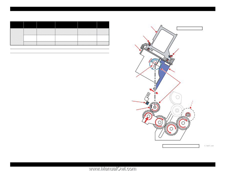
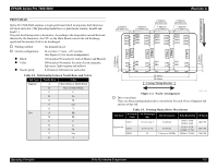
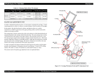
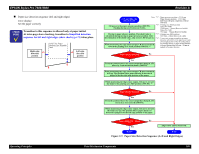
EPSON Stylus Pro 7600/9600 Table 2-3. Printing Modes (Drive Waveforms) Ink Type Waveform Ink Discharged Name (ng) Drive Frequency Print Resolution CR Speed Dye ink VSD1-Dye VSD2-Dye VSD4-Dye 13.8-27.6-41.5 5.4-9.5-23.0 2.5 8.64 KHz 8.64 KHz 2 shots at 6.84 KHz H360 x V360 H720 x V360 H720 x V720 H1440 x V720 H2880 x V1440 240 CPS 240 CPS 190 CPS PLATEN GAP ADJUSTMENT UNIT In order to maintain the print precision, it is necessary to maintain the carriage (= head) mounting position so that it is always a constant distance from the surface of the paper. In this printer, the print head nozzle surfaces and platen surface are variable mechanisms so that the gap between the paper printing surface and the head nozzle surface can be kept constant. The carriage has a 2-body construction with a sub-carriage on which the print heads are mounted attached to the carriage which forms the base. The sub-carriage moves in the vertical direction with respect to the paper surface. This movable system uses a cam. The sub-carriage to paper surface distance changes linearly from the cam (= PG) home position. When the carriage is in the HP position (= right end), the pump motor and the gear mounted on the cam shaft engage, the motor's rotation (reverse) drives the cam and the sub-carriage is positioned at the proper gap position. In order to maintain the distance between the print head nozzle surface and the paper properly, the thicknesses of the paper used are classified into 3 levels for PG setting, namely, PG small (1.3 mm), PG medium (2.2 mm) and PG large (2.7 mm). The sensors used in the platen gap adjustment unit are explained below. CR Guide Rail Bearing Carriage PG (Head SLID) HD_SLID Sensor HP Detection Flag Revision A Right Side of Carriage Bearing Sub-carriage (head mounted) Slide Gear Pump motor driving force (CCW) Operating Principles Right Side of Printer Mechanism Figure 2-4. Carriage Mechanical Unit and PG Adjustment Unit Print Mechanism Components 106
-
 1
1 -
2
-
3
-
4
-
5
-
6
-
7
-
8
-
9
-
10
-
11
-
12
-
13
-
14
-
15
-
16
-
17
-
18
-
19
-
20
-
21
-
22
-
23
-
24
-
25
-
26
-
27
-
28
-
29
-
30
-
31
-
32
-
33
-
34
-
35
-
36
-
37
-
38
-
39
-
40
-
41
-
42
-
43
-
44
-
45
-
46
-
47
-
48
-
49
-
50
-
51
-
52
-
53
-
54
-
55
-
56
-
57
-
58
-
59
-
60
-
61
-
62
-
63
-
64
-
65
-
66
-
67
-
68
-
69
-
70
-
71
-
72
-
73
-
74
-
75
-
76
-
77
-
78
-
79
-
80
-
81
-
82
-
83
-
84
-
85
-
86
-
87
-
88
-
89
-
90
-
91
-
92
-
93
-
94
-
95
-
96
-
97
-
98
-
99
-
100
-
 101
101 -
 102
102 -
 103
103 -
 104
104 -
 105
105 -
 106
106 -
 107
107 -
 108
108 -
 109
109 -
 110
110 -
 111
111 -
112
-
113
-
114
-
115
-
116
-
117
-
118
-
119
-
120
-
121
-
122
-
123
-
124
-
125
-
126
-
127
-
128
-
129
-
130
-
131
-
132
-
133
-
134
-
135
-
136
-
137
-
138
-
139
-
140
-
141
-
142
-
143
-
144
-
145
-
146
-
147
-
148
-
149
-
150
-
151
-
152
-
153
-
154
-
155
-
156
-
157
-
158
-
159
-
160
-
161
-
162
-
163
-
164
-
165
-
166
-
167
-
168
-
169
-
170
-
171
-
172
-
173
-
174
-
175
-
176
-
177
-
178
-
179
-
180
-
181
-
182
-
183
-
184
-
185
-
186
-
187
-
188
-
189
-
190
-
191
-
192
-
193
-
194
-
195
-
196
-
197
-
198
-
199
-
200
-
201
-
202
-
203
-
204
-
205
-
206
-
207
-
208
-
209
-
210
-
211
-
212
-
213
-
214
-
215
-
216
-
217
-
218
-
219
-
220
-
221
-
222
-
223
-
224
-
225
-
226
-
227
-
228
-
229
-
230
-
231
-
232
-
233
-
234
-
235
-
236
-
237
-
238
-
239
-
240
-
241
-
242
-
243
-
244
-
245
-
246
-
247
-
248
-
249
-
250
-
251
-
252
-
253
-
254
-
255
-
256
-
257
-
258
-
259
-
260
-
261
-
262
-
263
-
264
-
265
-
266
-
267
-
268
-
269
-
270
-
271
-
272
-
273
-
274
-
275
-
276
-
277
-
278
-
279
-
280
-
281
-
282
-
283
-
284
-
285
-
286
-
287
-
288
-
289
-
290
-
291
-
292
-
293
-
294
-
295
-
296
-
297
-
298
-
299
-
300
-
301
-
302
-
303
-
304
-
305
-
306
-
307
-
308
-
309
-
310
-
311
-
312
-
313
-
314
-
315
-
316
-
317
-
318
-
319
-
320
-
321
-
322
-
323
-
324
-
325
-
326
-
327
-
328
-
329
-
330
-
331
-
332
-
333
-
334
-
335
-
336
 |
 |