Epson 9600 Service Manual - Page 178
CR Encoder Sensor ASSY
 |
UPC - 010343841888
View all Epson 9600 manuals
Add to My Manuals
Save this manual to your list of manuals |
Page 178 highlights
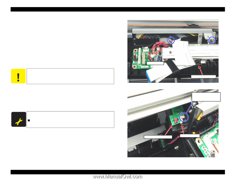
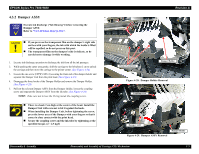
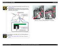
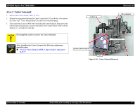
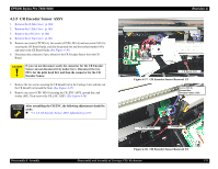
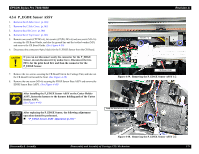
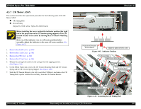
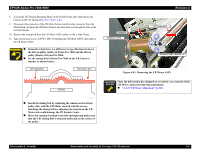
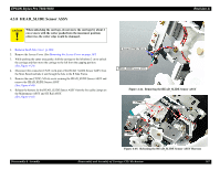
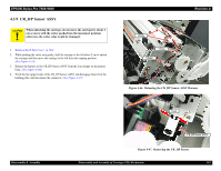
EPSON Stylus Pro 7600/9600 4.3.5 CR Encoder Sensor ASSY 1. Remove the R Side Cover. (p.160) 2. Remove the L Side Cover. (p.163) 3. Remove the I/H Cover. (p.164) 4. Remove the H Top Cover. (p.165) 5. Remove one screw (CPP M3×6), two screws (CP(W): M3×6) and one screw (M3×16) securing the CR Board Guide, and also the ground line and the toothed washer (M3), and remove the CR Board Guide.(See Figure 4-30) 6. Disconnect the connector (5-pin, white) for the CR Encoder Sensor from the CR Board. C A U T IO N If you can not disconnect easily the connector for the CR Encoder Sensor, do not disconnect it by undue force. Disconnect the two FFCs for the print head first and then the connector for the CR Encoder Sensor. 7. Remove the two screws securing the CR Board Unit in the Carriage Unit, and take out the CR Board Unit toward the front. (See Figure 4-37) 8. Remove one screw (CPP: M3×8) securing the CR_ENC ASSY, ground line, and washer (M3). Then remove the CR_ENC ASSY. (See Figure 4-38) A D JU S TM E N T R E Q U IR E D After assembling the CR ENC, the following adjustments should be made. „ "5.1.4.8 CR Encoder Sensor ASSY Adjustment (p.215)" Revision A Connector CR Board Unit Figure 4-37. CR Encoder Sensor Removal 1/2 Screw (M3×8) Ground line Toothed washer (M3) CR_ENC ASSY Ground line Disassembly & Assembly Figure 4-38. CR Encoder Sensor Removal 2/2 Disassembly and Assembly of Carriage (CR) Mechanism 178
-
 1
1 -
2
-
3
-
4
-
5
-
6
-
7
-
8
-
9
-
10
-
11
-
12
-
13
-
14
-
15
-
16
-
17
-
18
-
19
-
20
-
21
-
22
-
23
-
24
-
25
-
26
-
27
-
28
-
29
-
30
-
31
-
32
-
33
-
34
-
35
-
36
-
37
-
38
-
39
-
40
-
41
-
42
-
43
-
44
-
45
-
46
-
47
-
48
-
49
-
50
-
51
-
52
-
53
-
54
-
55
-
56
-
57
-
58
-
59
-
60
-
61
-
62
-
63
-
64
-
65
-
66
-
67
-
68
-
69
-
70
-
71
-
72
-
73
-
74
-
75
-
76
-
77
-
78
-
79
-
80
-
81
-
82
-
83
-
84
-
85
-
86
-
87
-
88
-
89
-
90
-
91
-
92
-
93
-
94
-
95
-
96
-
97
-
98
-
99
-
100
-
101
-
102
-
103
-
104
-
105
-
106
-
107
-
108
-
109
-
110
-
111
-
112
-
113
-
114
-
115
-
116
-
117
-
118
-
119
-
120
-
121
-
122
-
123
-
124
-
125
-
126
-
127
-
128
-
129
-
130
-
131
-
132
-
133
-
134
-
135
-
136
-
137
-
138
-
139
-
140
-
141
-
142
-
143
-
144
-
145
-
146
-
147
-
148
-
149
-
150
-
151
-
152
-
153
-
154
-
155
-
156
-
157
-
158
-
159
-
160
-
161
-
162
-
163
-
164
-
165
-
166
-
167
-
168
-
169
-
170
-
171
-
172
-
 173
173 -
 174
174 -
 175
175 -
 176
176 -
 177
177 -
 178
178 -
 179
179 -
 180
180 -
 181
181 -
 182
182 -
 183
183 -
184
-
185
-
186
-
187
-
188
-
189
-
190
-
191
-
192
-
193
-
194
-
195
-
196
-
197
-
198
-
199
-
200
-
201
-
202
-
203
-
204
-
205
-
206
-
207
-
208
-
209
-
210
-
211
-
212
-
213
-
214
-
215
-
216
-
217
-
218
-
219
-
220
-
221
-
222
-
223
-
224
-
225
-
226
-
227
-
228
-
229
-
230
-
231
-
232
-
233
-
234
-
235
-
236
-
237
-
238
-
239
-
240
-
241
-
242
-
243
-
244
-
245
-
246
-
247
-
248
-
249
-
250
-
251
-
252
-
253
-
254
-
255
-
256
-
257
-
258
-
259
-
260
-
261
-
262
-
263
-
264
-
265
-
266
-
267
-
268
-
269
-
270
-
271
-
272
-
273
-
274
-
275
-
276
-
277
-
278
-
279
-
280
-
281
-
282
-
283
-
284
-
285
-
286
-
287
-
288
-
289
-
290
-
291
-
292
-
293
-
294
-
295
-
296
-
297
-
298
-
299
-
300
-
301
-
302
-
303
-
304
-
305
-
306
-
307
-
308
-
309
-
310
-
311
-
312
-
313
-
314
-
315
-
316
-
317
-
318
-
319
-
320
-
321
-
322
-
323
-
324
-
325
-
326
-
327
-
328
-
329
-
330
-
331
-
332
-
333
-
334
-
335
-
336
 |
 |