Epson 9600 Service Manual - Page 230
Adjustment Menu Transition, Table 5-19., Panel Setting Item List, Panel Setting Item
 |
UPC - 010343841888
View all Epson 9600 manuals
Add to My Manuals
Save this manual to your list of manuals |
Page 230 highlights
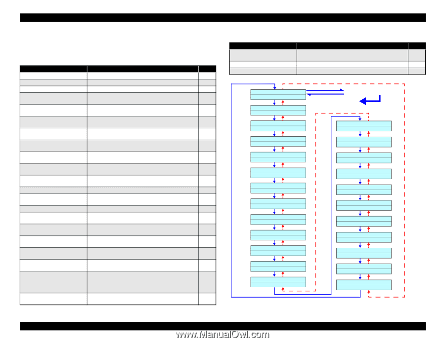
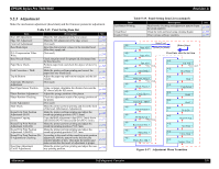
EPSON Stylus Pro 7600/9600 5.2.3 Adjustment Make the mechanism adjustment (head slant) and the firmware parameter adjustment. Table 5-19. Panel Setting Item List Item Rear AD Adjustment Edge AD Adjustment Front AD Adjustment Head Rank Input D/A Compensation Value Write Head Nozzle Check Paper Skew Check Feed Correction + T&B Top & Bottom Automatic Mechanism Adjustment Rear Paper Sensor Position Platen Position Adjustment Platen Position Checking Cutter Adjustment Slant Check Round Trip Print Position Adjustment (Bi-D) Parameter Copying (Bi-D) Round Trip Print Position Adjustment 2 (Bi-D2) Round Trip Print Position Adjustment 3 (Bi-D3) Round Trip Print Position (BiD Adjustment) Checking Head Gap Adjustment (Uni-D Adjustment) Description Make the AD adjustment of the rear sensor. Make the AD adjustment of the edge sensor. (Not used) Input the characteristic values for the installed head. After that, supply ink. (Not used) Check the print result for proper ink discharge from the head nozzles. Perform paper feed, and check the degree of skew by sensor. Make the printer perform printing and correct the paper feed rate (band feed). Adjust the paper top and bottom margins and the left margin. (Not used) Using cut paper, determine the distance between the XF sensor and the XR sensor. Adjust the sponge position of the platen. Check the adjustment result of the sponge position of the platen. (Not used) Make the printer perform printing and check the slant of the head. (Mechanism Adjustment) Make the printer perform printing and adjust the round trip printing position. (PG/1.2mm) Copy the Bi-D adjustment value (PG/1.2mm) above onto Bi-D2 (PG=0.7mm) and Bi-D3 (PG=2.1mm). Make the printer perform printing and adjust the round trip printing position. PG/0.7mm Make the printer perform printing and adjust the round trip printing position. PG/2.1mm According to the result of the round trip print position adjustment, shift the pattern by the theoretically required number of dots. Then print the pattern and make certain that the result of adjustment is proper. Make the printer perform printing and adjust the oneway printing position. See p. 231 p. 232 - p. 233 p. 236 p. 237 p. 238 p. 239 p. 242 - p. 243 p. 244 p. 245 - p. 246 p. 248 p. 251 p. 251 p. 251 p. 252 p. 253 Revision A Table 5-19. Panel Setting Item List (continued) Item Test Pattern Printing Clean Head Counter Clear Description Head nozzle checking and adjustment pattern (Input the serial number) Clean the tube and head using cleaning liquid. Clear various software counters. See p. 255 p. 256 p. 257 Adj : ? Rear AD ? [SelecType] [Pause] or [Items] [Enter] Start Adj : ? Edge AD ? Press Enter after the last item Adj : ? Adj : ? Frnt AD ? *Not Used Input Rank ? Adj : ? Adj : ? Cut Adj ? *Not Used Head Slant ? Adj : ? Adj : ? Write D/A Value ? *Not Used Check Nozzle ? Adj : ? Check Skew ? Adj : ? Feed Adj.+T&B ? Adj : ? Top & Bottom ? Adj : ? Adj : ? AT MechaAdj. ? *Not Used Rear Sensor Pos. ? Adj : ? Platen Pos. ? Adj : ? Platen Pos. Chk. ? Adj : ? Adj : ? Adj : ? Adj : ? Adj : ? Adj : ? Adj : ? Adj : ? Adj : ? Bi-d ? CopyParam. Bi-d2 ? Bi-d3 ? Bi-d Chk. ? Head LR Adj. Test Print ? Clean Head ? Counter Clear ? Figure 5-17. Adjustment Menu Transition Adjustment Self-diagnostic Function 230
-
 1
1 -
2
-
3
-
4
-
5
-
6
-
7
-
8
-
9
-
10
-
11
-
12
-
13
-
14
-
15
-
16
-
17
-
18
-
19
-
20
-
21
-
22
-
23
-
24
-
25
-
26
-
27
-
28
-
29
-
30
-
31
-
32
-
33
-
34
-
35
-
36
-
37
-
38
-
39
-
40
-
41
-
42
-
43
-
44
-
45
-
46
-
47
-
48
-
49
-
50
-
51
-
52
-
53
-
54
-
55
-
56
-
57
-
58
-
59
-
60
-
61
-
62
-
63
-
64
-
65
-
66
-
67
-
68
-
69
-
70
-
71
-
72
-
73
-
74
-
75
-
76
-
77
-
78
-
79
-
80
-
81
-
82
-
83
-
84
-
85
-
86
-
87
-
88
-
89
-
90
-
91
-
92
-
93
-
94
-
95
-
96
-
97
-
98
-
99
-
100
-
101
-
102
-
103
-
104
-
105
-
106
-
107
-
108
-
109
-
110
-
111
-
112
-
113
-
114
-
115
-
116
-
117
-
118
-
119
-
120
-
121
-
122
-
123
-
124
-
125
-
126
-
127
-
128
-
129
-
130
-
131
-
132
-
133
-
134
-
135
-
136
-
137
-
138
-
139
-
140
-
141
-
142
-
143
-
144
-
145
-
146
-
147
-
148
-
149
-
150
-
151
-
152
-
153
-
154
-
155
-
156
-
157
-
158
-
159
-
160
-
161
-
162
-
163
-
164
-
165
-
166
-
167
-
168
-
169
-
170
-
171
-
172
-
173
-
174
-
175
-
176
-
177
-
178
-
179
-
180
-
181
-
182
-
183
-
184
-
185
-
186
-
187
-
188
-
189
-
190
-
191
-
192
-
193
-
194
-
195
-
196
-
197
-
198
-
199
-
200
-
201
-
202
-
203
-
204
-
205
-
206
-
207
-
208
-
209
-
210
-
211
-
212
-
213
-
214
-
215
-
216
-
217
-
218
-
219
-
220
-
221
-
222
-
223
-
224
-
 225
225 -
 226
226 -
 227
227 -
 228
228 -
 229
229 -
 230
230 -
 231
231 -
 232
232 -
 233
233 -
 234
234 -
 235
235 -
236
-
237
-
238
-
239
-
240
-
241
-
242
-
243
-
244
-
245
-
246
-
247
-
248
-
249
-
250
-
251
-
252
-
253
-
254
-
255
-
256
-
257
-
258
-
259
-
260
-
261
-
262
-
263
-
264
-
265
-
266
-
267
-
268
-
269
-
270
-
271
-
272
-
273
-
274
-
275
-
276
-
277
-
278
-
279
-
280
-
281
-
282
-
283
-
284
-
285
-
286
-
287
-
288
-
289
-
290
-
291
-
292
-
293
-
294
-
295
-
296
-
297
-
298
-
299
-
300
-
301
-
302
-
303
-
304
-
305
-
306
-
307
-
308
-
309
-
310
-
311
-
312
-
313
-
314
-
315
-
316
-
317
-
318
-
319
-
320
-
321
-
322
-
323
-
324
-
325
-
326
-
327
-
328
-
329
-
330
-
331
-
332
-
333
-
334
-
335
-
336
 |
 |