Epson 9600 Service Manual - Page 199
Maintenance ASSY Removal
 |
UPC - 010343841888
View all Epson 9600 manuals
Add to My Manuals
Save this manual to your list of manuals |
Page 199 highlights
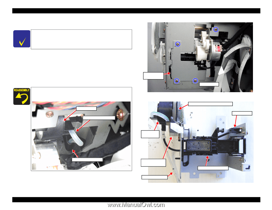
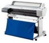
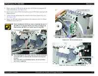
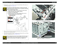
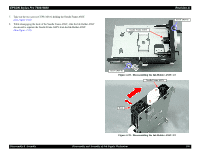
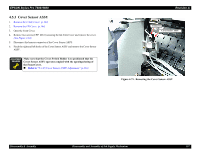
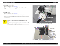
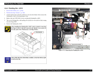
EPSON Stylus Pro 7600/9600 4.6.1 Maintenance ASSY Removal CHECK P O IN T When you replace the Maintenance ASSY, ink can spill from the ink tube connected to the pump assembly. Disconnect the ink tubes carefully so that ink will not spill. Revision A 1. Remove the R Side Cover. (p.160) 2. Remove the Access Cover. (See Removing the Access Cover on page 167) 3. Disconnect the connector (CN17) of the Pump Motor ASSY. 4. At the rear of the printer body, remove the four screws securing the Maintenance ASSY, and remove the Maintenance ASSY from the printer body. (See Figure 4-72) After installing the Maintenance ASSY, insert the waste ink tube (thin) of the Pump Motor ASSY into the waste ink tube (thick) of the Flushing Box ASSY to the depth using tweezers. Pump ASSY Waste ink tube (thin) Maintenance ASSY Screw x4 Figure 4-72. Removing the Maintenance ASSY Cleaner Head (Wiper) (p.203) Valve ASSY Pump ASSY (p.201) Flushing Box ASSY Pump Motor ASSY (p.200) Waste ink tube Cap ASSY (p.200) Figure 4-73. Maintenance ASSY Disassembly & Assembly Disassembly and Assembly of Cleaning Mechanism 199
-
 1
1 -
2
-
3
-
4
-
5
-
6
-
7
-
8
-
9
-
10
-
11
-
12
-
13
-
14
-
15
-
16
-
17
-
18
-
19
-
20
-
21
-
22
-
23
-
24
-
25
-
26
-
27
-
28
-
29
-
30
-
31
-
32
-
33
-
34
-
35
-
36
-
37
-
38
-
39
-
40
-
41
-
42
-
43
-
44
-
45
-
46
-
47
-
48
-
49
-
50
-
51
-
52
-
53
-
54
-
55
-
56
-
57
-
58
-
59
-
60
-
61
-
62
-
63
-
64
-
65
-
66
-
67
-
68
-
69
-
70
-
71
-
72
-
73
-
74
-
75
-
76
-
77
-
78
-
79
-
80
-
81
-
82
-
83
-
84
-
85
-
86
-
87
-
88
-
89
-
90
-
91
-
92
-
93
-
94
-
95
-
96
-
97
-
98
-
99
-
100
-
101
-
102
-
103
-
104
-
105
-
106
-
107
-
108
-
109
-
110
-
111
-
112
-
113
-
114
-
115
-
116
-
117
-
118
-
119
-
120
-
121
-
122
-
123
-
124
-
125
-
126
-
127
-
128
-
129
-
130
-
131
-
132
-
133
-
134
-
135
-
136
-
137
-
138
-
139
-
140
-
141
-
142
-
143
-
144
-
145
-
146
-
147
-
148
-
149
-
150
-
151
-
152
-
153
-
154
-
155
-
156
-
157
-
158
-
159
-
160
-
161
-
162
-
163
-
164
-
165
-
166
-
167
-
168
-
169
-
170
-
171
-
172
-
173
-
174
-
175
-
176
-
177
-
178
-
179
-
180
-
181
-
182
-
183
-
184
-
185
-
186
-
187
-
188
-
189
-
190
-
191
-
192
-
193
-
 194
194 -
 195
195 -
 196
196 -
 197
197 -
 198
198 -
 199
199 -
 200
200 -
 201
201 -
 202
202 -
 203
203 -
 204
204 -
205
-
206
-
207
-
208
-
209
-
210
-
211
-
212
-
213
-
214
-
215
-
216
-
217
-
218
-
219
-
220
-
221
-
222
-
223
-
224
-
225
-
226
-
227
-
228
-
229
-
230
-
231
-
232
-
233
-
234
-
235
-
236
-
237
-
238
-
239
-
240
-
241
-
242
-
243
-
244
-
245
-
246
-
247
-
248
-
249
-
250
-
251
-
252
-
253
-
254
-
255
-
256
-
257
-
258
-
259
-
260
-
261
-
262
-
263
-
264
-
265
-
266
-
267
-
268
-
269
-
270
-
271
-
272
-
273
-
274
-
275
-
276
-
277
-
278
-
279
-
280
-
281
-
282
-
283
-
284
-
285
-
286
-
287
-
288
-
289
-
290
-
291
-
292
-
293
-
294
-
295
-
296
-
297
-
298
-
299
-
300
-
301
-
302
-
303
-
304
-
305
-
306
-
307
-
308
-
309
-
310
-
311
-
312
-
313
-
314
-
315
-
316
-
317
-
318
-
319
-
320
-
321
-
322
-
323
-
324
-
325
-
326
-
327
-
328
-
329
-
330
-
331
-
332
-
333
-
334
-
335
-
336
 |
 |