Epson 9600 Service Manual - Page 114
Paper Feed Mechanical Unit Stylus Pro 7600 2/2, Table 2-5., Modes
 |
UPC - 010343841888
View all Epson 9600 manuals
Add to My Manuals
Save this manual to your list of manuals |
Page 114 highlights
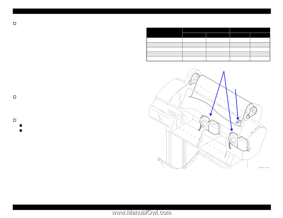
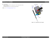
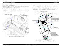
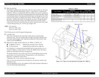
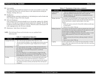
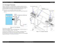
EPSON Stylus Pro 7600/9600 † Paper Suction Fans The printer is equipped with suction fans in the lower space in the rear. The space in the column direction behind Paper Guide L2 is divided into 2 compartments (Stylus Pro 7600) or 3 compartments (Stylus Pro 9600), and one fan is mounted in each compartment. By drawing air through multiple holes punched in Paper Guide L2 in the back surface of the paper path and blowing it out through the rear of the printer housing, suction is applied to the surfaces of Paper Guides L1 and L2 and the paper is stabilized (prevented from flying up) as it passes through the printer. The suction fans undergo air flow control (fan rotation duty control), which is carried out by firmware control based on the printer's operating state (when paper is set and during printing, etc.) and the type of paper used. NOTE: Fans mounted Stylus Pro 7600: 2 fans Stylus Pro 9600: 3 fans The following sensors aid in the paper feeding process. † P_REAR sensor This sensor is attached to the Upper Paper Guide and is an optical (photoreflective) sensor. This sensor detects the rear edge of the paper and detects the front edge when the paper is first loaded in the paper path. The position of this sensor is stored in EEPROM. † Paper set lever, paper thickness detection (P_THICK, P_THICK_0.3) „ P_THICK_0.3 Sensor: Transmission type photosensor, left side. „ P_THICK Sensor: Transmission type photosensor, right side. The mechanism is so designed that the threshold values for paper thickness are 0.3 ~ 0.4 mm (P_THICK_0.3 sensor) and 0.8 ~ 0.9 mm (P_THICK sensor). The sensors operate just when the pressure lever is brought down. The designed detection values of the sensors for the UP and DOWN positions of the pressure lever are 0.3 mm and 0.8 mm. The pressure lever in the UP position is detected by a combination of both sensors. "Thick paper state" occurs when the connections are open. There is no error processing since this mechanism can not determine whether it has broke down or not. Since the mechanism is always in recognition of thick paper, printing on thin paper is carry out with the platen gap kept large. Revision A Paper Thickness Below 0.3 mm 0.3 mm to 0.8 mm incl. 0.81 mm or above Connector not connected Pressure release (Hi-Up) Table 2-5. Modes Shield Plate Sensor Output P_THICK_0.3 P_THICK P_THICK_0.3 P_THICK Absent (Open) Absent (Open) L L Present (Closed) Absent (Open) H L Present (Closed) Present (Closed) H H - - H H - - L H Paper suction fans P-Rear sensor Figure 2-13. Paper Feed Mechanical Unit (Stylus Pro 7600) 2/2 Operating Principles Print Mechanism Components 114
-
 1
1 -
2
-
3
-
4
-
5
-
6
-
7
-
8
-
9
-
10
-
11
-
12
-
13
-
14
-
15
-
16
-
17
-
18
-
19
-
20
-
21
-
22
-
23
-
24
-
25
-
26
-
27
-
28
-
29
-
30
-
31
-
32
-
33
-
34
-
35
-
36
-
37
-
38
-
39
-
40
-
41
-
42
-
43
-
44
-
45
-
46
-
47
-
48
-
49
-
50
-
51
-
52
-
53
-
54
-
55
-
56
-
57
-
58
-
59
-
60
-
61
-
62
-
63
-
64
-
65
-
66
-
67
-
68
-
69
-
70
-
71
-
72
-
73
-
74
-
75
-
76
-
77
-
78
-
79
-
80
-
81
-
82
-
83
-
84
-
85
-
86
-
87
-
88
-
89
-
90
-
91
-
92
-
93
-
94
-
95
-
96
-
97
-
98
-
99
-
100
-
101
-
102
-
103
-
104
-
105
-
106
-
107
-
108
-
 109
109 -
 110
110 -
 111
111 -
 112
112 -
 113
113 -
 114
114 -
 115
115 -
 116
116 -
 117
117 -
 118
118 -
 119
119 -
120
-
121
-
122
-
123
-
124
-
125
-
126
-
127
-
128
-
129
-
130
-
131
-
132
-
133
-
134
-
135
-
136
-
137
-
138
-
139
-
140
-
141
-
142
-
143
-
144
-
145
-
146
-
147
-
148
-
149
-
150
-
151
-
152
-
153
-
154
-
155
-
156
-
157
-
158
-
159
-
160
-
161
-
162
-
163
-
164
-
165
-
166
-
167
-
168
-
169
-
170
-
171
-
172
-
173
-
174
-
175
-
176
-
177
-
178
-
179
-
180
-
181
-
182
-
183
-
184
-
185
-
186
-
187
-
188
-
189
-
190
-
191
-
192
-
193
-
194
-
195
-
196
-
197
-
198
-
199
-
200
-
201
-
202
-
203
-
204
-
205
-
206
-
207
-
208
-
209
-
210
-
211
-
212
-
213
-
214
-
215
-
216
-
217
-
218
-
219
-
220
-
221
-
222
-
223
-
224
-
225
-
226
-
227
-
228
-
229
-
230
-
231
-
232
-
233
-
234
-
235
-
236
-
237
-
238
-
239
-
240
-
241
-
242
-
243
-
244
-
245
-
246
-
247
-
248
-
249
-
250
-
251
-
252
-
253
-
254
-
255
-
256
-
257
-
258
-
259
-
260
-
261
-
262
-
263
-
264
-
265
-
266
-
267
-
268
-
269
-
270
-
271
-
272
-
273
-
274
-
275
-
276
-
277
-
278
-
279
-
280
-
281
-
282
-
283
-
284
-
285
-
286
-
287
-
288
-
289
-
290
-
291
-
292
-
293
-
294
-
295
-
296
-
297
-
298
-
299
-
300
-
301
-
302
-
303
-
304
-
305
-
306
-
307
-
308
-
309
-
310
-
311
-
312
-
313
-
314
-
315
-
316
-
317
-
318
-
319
-
320
-
321
-
322
-
323
-
324
-
325
-
326
-
327
-
328
-
329
-
330
-
331
-
332
-
333
-
334
-
335
-
336
 |
 |