Epson 9600 Service Manual - Page 208
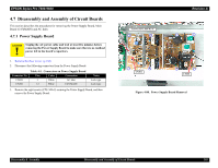
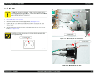
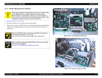
Disassembly & Assembly, Disassembly and Assembly of Circuit Boards
 |
UPC - 010343841888
View all Epson 9600 manuals
Add to My Manuals
Save this manual to your list of manuals |
Page 208 highlights
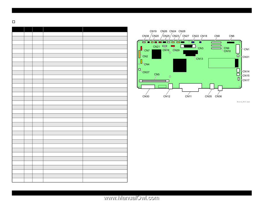
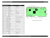
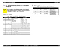
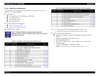
EPSON Stylus Pro 7600/9600 † Main Board Connector List CN.No. Pins Color Connection CN1 12 White P/S board CN2 16 PANEL CN3 36 H-UDI36 CN4 5 Yellow D/A_OUT CN5 90 ROM_DIMM CN6 21 CSIC CN7 5 Red S_I/O(DEBUGER) CN8 24 CR_FFC1 CN9 24 CR_FFC3 CN10 24 CR_FFC2 CN11 36 IEEE1284 (parallel port) CN12 4 USB CN13 36 TYPE_B CN14 3 White CR_MOT CN15 2 White PF_MOT CN16 5 White PF_ENC CN17 4 White PUMP_MOT CN18 2 Blue P/S_FAN CN19 2 Black FAN1 CN20 2 Yellow FAN2 CN21 2 Red FAN3 CN22 3 Blue P_THICK0.3 CN23 3 Yellow COVER_L CN24 3 White CR_ORG CN25 3 Black I/H_LEVER CN26 3 Red P_THICK CN27 4 Black P_REAR CN28 4 Yellow P_FRONT CN29 4 Red HD_SLID CN30 15 ROLL_UNIT (option unit) CN31 2 White H_FAN CN33 3 White RESET CN35 4 USB2.0 CN36 8 IEEE1394 CN37 2 HDD_PS Remarks Lock type FFC, lock type (Not used) FFC (Not used) FFC, lock type FFC, lock type FFC, lock type (Not used) Lock type, with relay connector Lock type, with relay connector With relay connector With relay connector With relay connector * Stylus Pro 9600 only (Not used) (Not used) * Stylus Pro 9600 only Right side (AC side) (Not used) (Not used) Figure 4-85. Connector Locations Disassembly & Assembly Disassembly and Assembly of Circuit Boards Revision A 208
-
 1
1 -
2
-
3
-
4
-
5
-
6
-
7
-
8
-
9
-
10
-
11
-
12
-
13
-
14
-
15
-
16
-
17
-
18
-
19
-
20
-
21
-
22
-
23
-
24
-
25
-
26
-
27
-
28
-
29
-
30
-
31
-
32
-
33
-
34
-
35
-
36
-
37
-
38
-
39
-
40
-
41
-
42
-
43
-
44
-
45
-
46
-
47
-
48
-
49
-
50
-
51
-
52
-
53
-
54
-
55
-
56
-
57
-
58
-
59
-
60
-
61
-
62
-
63
-
64
-
65
-
66
-
67
-
68
-
69
-
70
-
71
-
72
-
73
-
74
-
75
-
76
-
77
-
78
-
79
-
80
-
81
-
82
-
83
-
84
-
85
-
86
-
87
-
88
-
89
-
90
-
91
-
92
-
93
-
94
-
95
-
96
-
97
-
98
-
99
-
100
-
101
-
102
-
103
-
104
-
105
-
106
-
107
-
108
-
109
-
110
-
111
-
112
-
113
-
114
-
115
-
116
-
117
-
118
-
119
-
120
-
121
-
122
-
123
-
124
-
125
-
126
-
127
-
128
-
129
-
130
-
131
-
132
-
133
-
134
-
135
-
136
-
137
-
138
-
139
-
140
-
141
-
142
-
143
-
144
-
145
-
146
-
147
-
148
-
149
-
150
-
151
-
152
-
153
-
154
-
155
-
156
-
157
-
158
-
159
-
160
-
161
-
162
-
163
-
164
-
165
-
166
-
167
-
168
-
169
-
170
-
171
-
172
-
173
-
174
-
175
-
176
-
177
-
178
-
179
-
180
-
181
-
182
-
183
-
184
-
185
-
186
-
187
-
188
-
189
-
190
-
191
-
192
-
193
-
194
-
195
-
196
-
197
-
198
-
199
-
200
-
201
-
202
-
 203
203 -
 204
204 -
 205
205 -
 206
206 -
 207
207 -
 208
208 -
 209
209 -
 210
210 -
 211
211 -
 212
212 -
 213
213 -
214
-
215
-
216
-
217
-
218
-
219
-
220
-
221
-
222
-
223
-
224
-
225
-
226
-
227
-
228
-
229
-
230
-
231
-
232
-
233
-
234
-
235
-
236
-
237
-
238
-
239
-
240
-
241
-
242
-
243
-
244
-
245
-
246
-
247
-
248
-
249
-
250
-
251
-
252
-
253
-
254
-
255
-
256
-
257
-
258
-
259
-
260
-
261
-
262
-
263
-
264
-
265
-
266
-
267
-
268
-
269
-
270
-
271
-
272
-
273
-
274
-
275
-
276
-
277
-
278
-
279
-
280
-
281
-
282
-
283
-
284
-
285
-
286
-
287
-
288
-
289
-
290
-
291
-
292
-
293
-
294
-
295
-
296
-
297
-
298
-
299
-
300
-
301
-
302
-
303
-
304
-
305
-
306
-
307
-
308
-
309
-
310
-
311
-
312
-
313
-
314
-
315
-
316
-
317
-
318
-
319
-
320
-
321
-
322
-
323
-
324
-
325
-
326
-
327
-
328
-
329
-
330
-
331
-
332
-
333
-
334
-
335
-
336
 |
 |